| Station Unit × 1 | Lamp Units × 4 | Ethernet Cable × 1 |
 |  |  |
| AC Adapter × 1 | USB Cable × 1 | Setup Guide × 1 |
 |  |  |
| Number Cover Frames(1 each of numbers 1 to 4) | ||
 |
FlexTally
FlexTally is a tally lamp system designed for easy operability and is available at a price range that means even small studios or streaming sites can look to add it to their multi-camera set-ups.
Thank you for purchasing FlexTally. Please carefully read this online manual and use the product.
Install “FlexTally Utility” from this page and update firmware of FlexTally station. See this page for updating firmware.
Firmware updates are no longer available for FlexTally.
1.Before Using FlexTally
Box Contents
Specifications
| Station | Lamp | |
|---|---|---|
| Size (WxDxH) | 128 × 77 × 28 mm | 100 × 60 × 50 mm |
| Weight | 142g | 164g |
| Power Supply | Micro-USB | Micro-USB/ Internal Battery |
| Wireless Connection | 315MHz(JP)/433MHz(US/EU) | 315MHz(JP)/433MHz(US/EU) |
| Wired Connection | RS-485 Serial | RS-485 Serial |
| Max. Connectable Lamps | 16(※) | – |
| Max. Battery Runtime | N/A | 6 Hours |
| Battery Charging Time | N/A | 2 Hours |
| Brightness Adjustment | N/A | 4 Steps (Preview: Green, On-air: Red) |
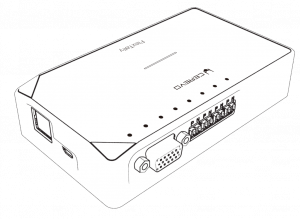
Product Overview
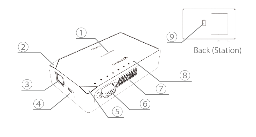
Station Unit
| Name | Description | |
|---|---|---|
| ① | Status LED | Illuminates according to power supply and status. |
| ② | Function2 Button | Used to switch station settings and functions. |
| ③ | Ethernet Port | Used to connect with a switcher such as LiveWedge that can acquire a tally signal via Ethernet. |
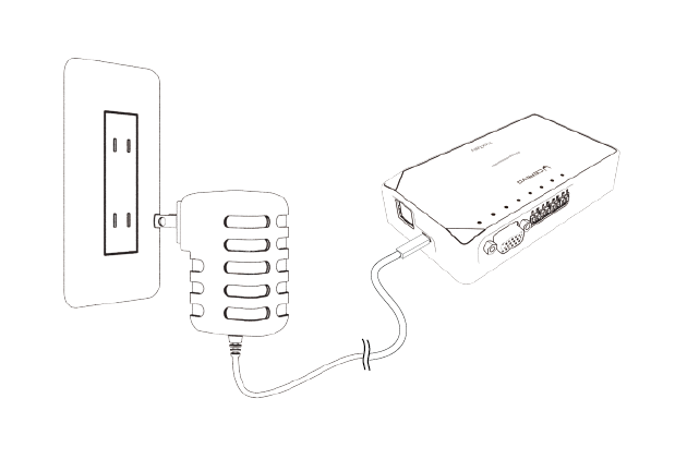
| ④ | Micro USB Port | Used for power supply, connect the included AC adapter. |
| ⑤ | Function1 Button | Used to switch station settings and functions. |
| ⑥ | GPIO Port | Used to connect with the switcher that outputs a tally signal via GPIO. ※A separate connection cable is necessary for connection with the switcher. |
| ⑦ | Wire Port | Used when connecting with a lamp in wired mode. ※Single core pair cable is required. |
| ⑧ | Tally LED | The status of the tally signal acquired from the switcher is indicated by the LED. |
| ⑨ | DIP Switch | Used to switch station settings. |
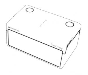
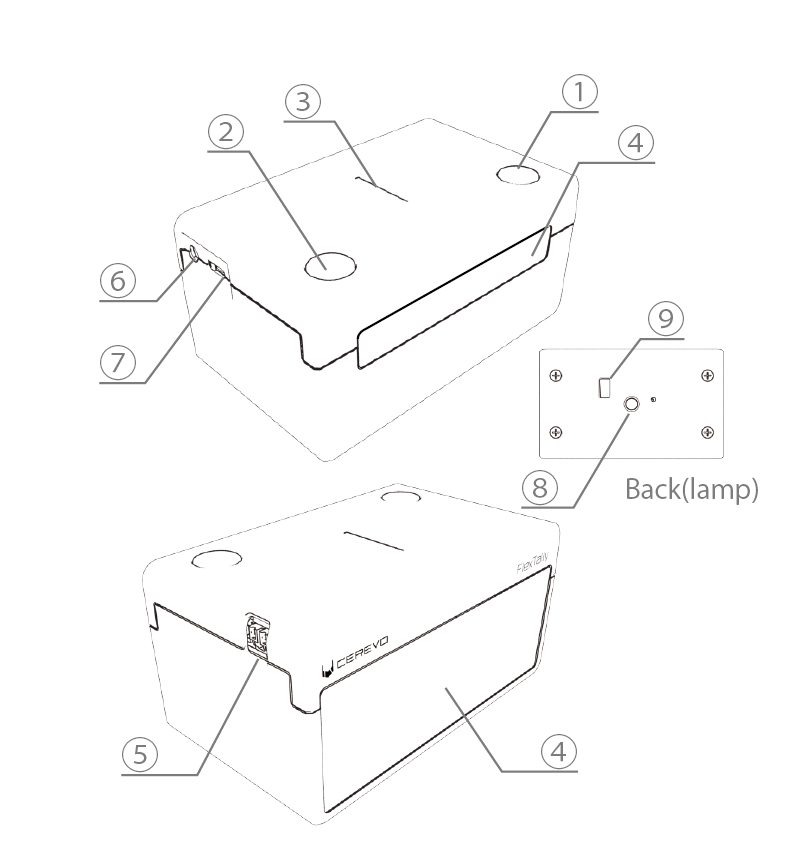
Lamp Unit
| Name | Description | |
|---|---|---|
| ① | Power Button | Press and hold to switch the power on or off. |
| ② | Function Button | Used to switch lamp settings and functions. |
| ③ | Status LED | Illuminates according to power supply and status. |
| ④ | Tally lamp (Front/Back) | Illuminates when the tally signal set on the lamp is acquired from the switcher. |
| ⑤ | Wire Port | Used when connecting with the station in wired mode. ※Single core pair cable is required. |
| ⑥ | GPIO Port | Tally signal is output as GPIO. For details,refer to "Lamp GPIO output". |
| ⑦ | Micro USB Port | Used for power supply and battery charging. |
| ⑧ | Tripod Hole | Used when attaching to a tripod,etc. |
| ⑨ | DIP Switch | Used to switch lamp settings. |
Hardware Precautions
- Use this product in an environment that has a temperature between 5~35°C (41~95°F) and a humidity between 10~90%.
- A very low or very high temperature may shorten the battery life and could temporarily stop the device as well.
- Do not use any AC/electrical adapters other than the one provided. Doing so could damage the product or result in a fire.
- Use an adapter with surge protection and only in electrical outlets supplying the electric currents specified on the AC adapter.
- Do not use this product in any location that is subjected to direct sunlight, water, humidity, fire, or extremely high temperatures. Doing so could damage the product or result in electric shock.
Regulation Compliance
This equipment complies with FCC RF radiation exposure limits set forth for an uncontrolled environment. This equipment should be installed and operated with a minimum distance of 20 centimeters between the radiator and your body.
Warning: Changes or modifications to this unit not expressly approved by the party responsible for compliance could void the user’s authority to operate the equipment.
Note: This equipment has been tested and found to comply with the limits for a Class B digital device, pursuant to Part 15 of the FCC Rules. These limits are designed to provide reasonable protection against harmful interference in a residential installation. This equipment generates, uses and can radiate radio frequency energy and, if not installed and used in accordance with the instructions, may cause harmful interference to radio communications. However, there is no guarantee that interference will not occur in a particular installation. If this equipment does cause harmful interference to radio or television reception, which can be determined by turning the equipment off and on, the user is encouraged to try to correct the interference by one or more of the following measures:
- Reorient or relocate the receiving antenna.
- Increase the separation between the equipment and receiver.
- Connect the equipment into an outlet on a circuit different from that to which the receiver is connected.
- Consult the dealer or an experienced radio/TV technician for help.
This device complies with Industry Canada license-exempt RSS standard(s). Operation is subject to the following two conditions: (1) this device may not cause interference, and (2) this device must accept any interference, including interference that may cause undesired operation of the device.
Le présent appareil est conforme aux CNR d’Industrie Canada applicables aux appareils radio exempts de licence. L’exploitation est autorisée aux deux conditions suivantes : (1) l’appareil ne doit pas produire de brouillage, et (2) l’utilisateur de l’appareil doit accepter tout brouillage radioélectrique subi, même si le brouillage est susceptible d’en compromettre le fonctionnement.
2.Preparation
Install PC Application
“FlexTally Utility” is an application that updates the firmware of the FlexTally Station Unit and sets the connection with the switcher used in Ethernet connection mode.
FlexTally Utility does not need to be installed if the switcher connection is GPIO mode.
Download
Please download the application from the link below.
The current latest version is ver 2.0.0. If an earlier version of the application is already installed on the setting PC, please uninstall it and download the installer from the link below, and install the application again on the setting PC.
FlexTallyUtility (Windows)※ Supported OS: Windows 10
※ PC requirements: Memory 2GB or more, free space HDD 100MB or more required for installation
FlexTallyUtility (MacOS Intel Mac)※ Supported OS: MacOS High Sierra 10.13 or later
※ PC requirements: Free space HDD 100MB or more required for installation
FlexTallyUtility (MacOS Apple silicon Mac)※ Supported OS: MacOS High Sierra 10.13 or later
※ PC requirements: Free space HDD 100MB or more required for installation
If you want to connect with Wirecast, please install “FlexTally For Wirecast” below.
※As of May 2023, connection settings with Wirecast are only supported by the FlexTally Utility Windows version. If you want to use Wirecast on a MacOS-equipped PC, please prepare a Windows OS PC separately as a setting PC.
FlexTally For Wirecast(Windows)※ Supported OS: Windows 10
※ PC requirements: Memory 2GB or more, free space HDD 100MB or more required for installation
Install
Windows
1.Double-click the downloaded installer to run it.
2.Follow the instructions on the screen to install.
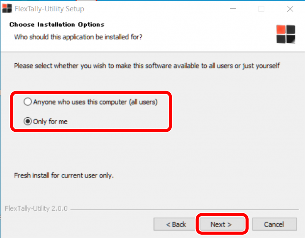
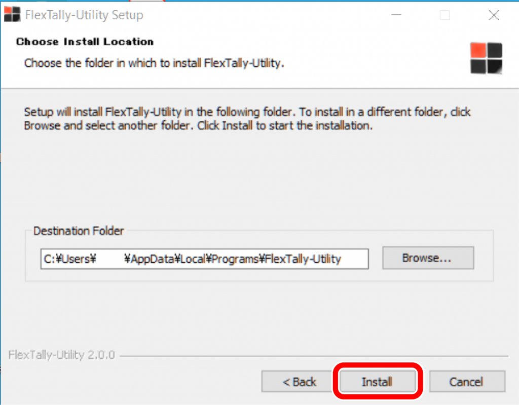
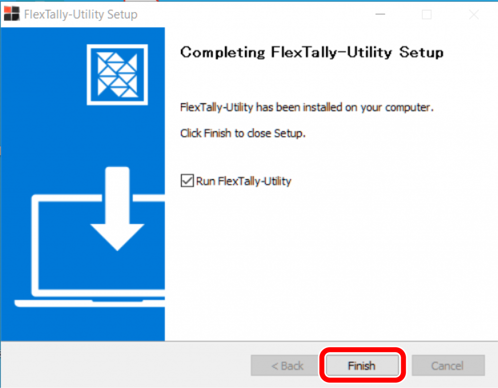
3.FlexTally Utility shortcut icon will appear on your desktop when the installation is complete.
Mac OS
1.Double-click the downloaded installer to run it.
2.Follow the instructions on the screen to install.
3.FlexTally Utility shortcut icon will appear on your Launchpad when the installation is complete.
Station Settings
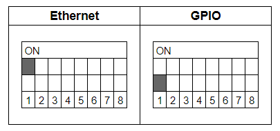
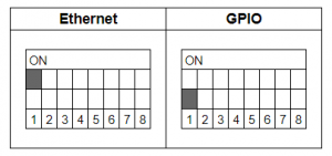
DIP Switch Settings
GPIO Settings
1.Connection mode with switcher
2.GPIO switcher type
Please change GPIO type after referring to here.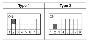
3.GPIO preview availability
- ON: Program&Preview (max 4ch)
- OFF: Program (max 8ch)
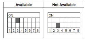
4.GPIO signal polarity
- ON:Normal
- OFF:Reverse
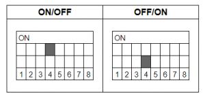
Station ID Settings
Up to 7 groups can be set up by using DIP switches No.5 to 7.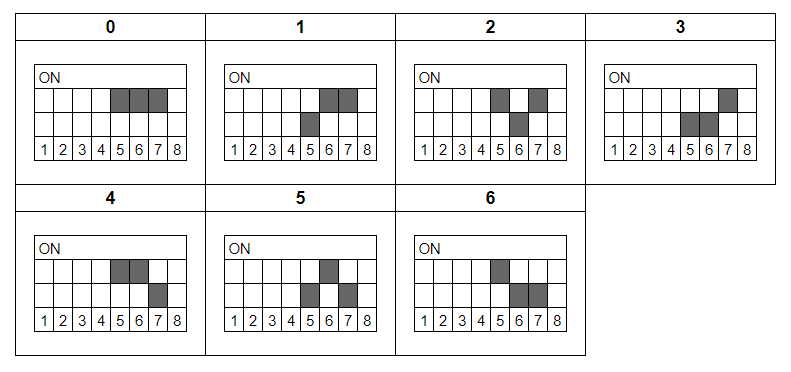
※The setting to turn off all of No.5 to 7 is reserved for the system.
Connection Mode with Station
By using the DIP switch No.8, the connection mode setting with the station can be changed.
Lamp Settings
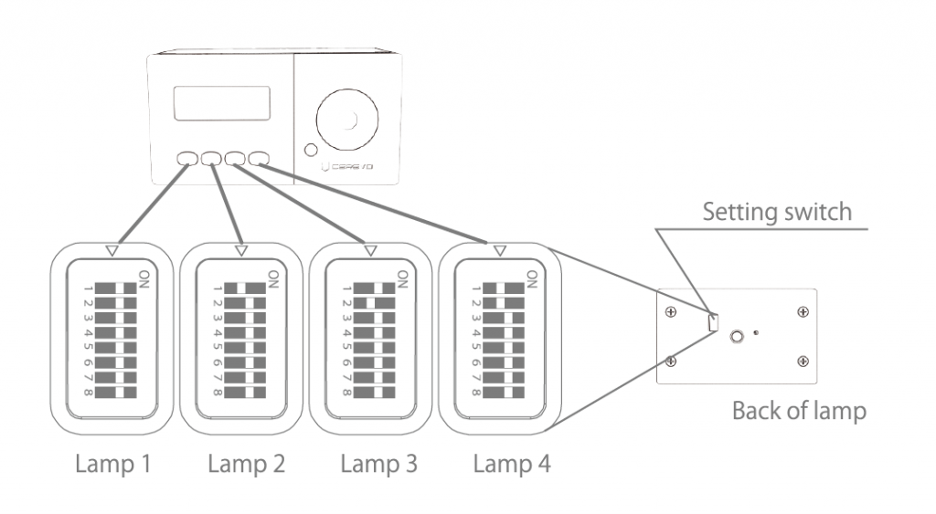
DIP Switch Settings
Channel Settings
Up to 16 channels can be set by using DIP switches No.1 to 4.
Station ID Settings
Up to 7 groups can be set up by using DIP switches No.5 to 7.
※The setting to turn off all of No.5 to 7 is reserved for the system.
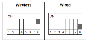
Connection Mode with Station
By using the DIP switch No.8, the connection mode setting with the station can be changed.
Brightness Settings
By pressing the FUNCTION button you can set the brightness in 4 steps.
Station and Lamp Connection
Connection Procedure
1.To connect a station to a lamp, you need to make the station group number the same as the group of lamps. Both stations and lamps can be set in up to 7 groups by using DIP switches No.5 to 7.

※The setting to turn off all of No.5 to 7 is reserved for the system.
2.Wired and wireless connections are available for stations and lamps.
- Wired and wireless connections are available for stations and lamps. To use a wired connection, connect the station and the WIRE port of the lamp with a single core pair cable, make sure that P and P and N and N terminals match on the stations and lamp.
- Wireless Connection To use a wireless connection, turn on DIP switch No. 8 on the station and lamp.
Also turn OFF the station and lamp DIP switch No. 8. Please refer to herehere for details.
※A single core pair cable is not included with the product. Please purchase separately.
Status LED
The LED colors will change depending on the status of the Station and Lamps.
Station
| LED Color | Status |
|---|---|
| Blue | Power On |
Lamp
| LED Color | Status |
|---|---|
| Blue | Power On |
| Yellow | Low Battery |
| Yellow | Powered Off and Charging Battery |
3.Connect with Switchers
Turning On/Off the Preview Indicator (Green Lamp)
About the Preview Indicator
With FlexTally Utility software ver. 1.2.0 and FlexTally firmware Rev. 0029 you have the choice to turn on or off the preview indicator (green lamp) when FlexTally is connected via Ethernet to a supported switcher.
Preparation
- Prepare a PC for setting.
- Install “FlexTally Utility” on the setting PC. Click here for installation instructions.
- Please update the firmware of the FlexTally Station Unit to the latest version. See here for how to update.
- Set DIP switch No. 1 on the Station Unit to ON and set the connection method to “Ethernet” setting.
How to Change Settings
You can configure the preview indicator (green lamp) to on/off in the Switcher (Ethernet Mode) screen in FlexTally Utility.
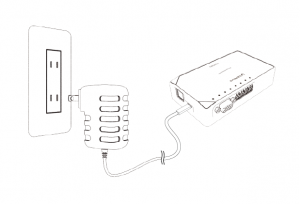
- Connect the Station Unit, the switcher and the setup PC to the same network.
- Connect the AC adapter to the Station Unit and turn it on. When the power turns on, the status LED lights up blue.

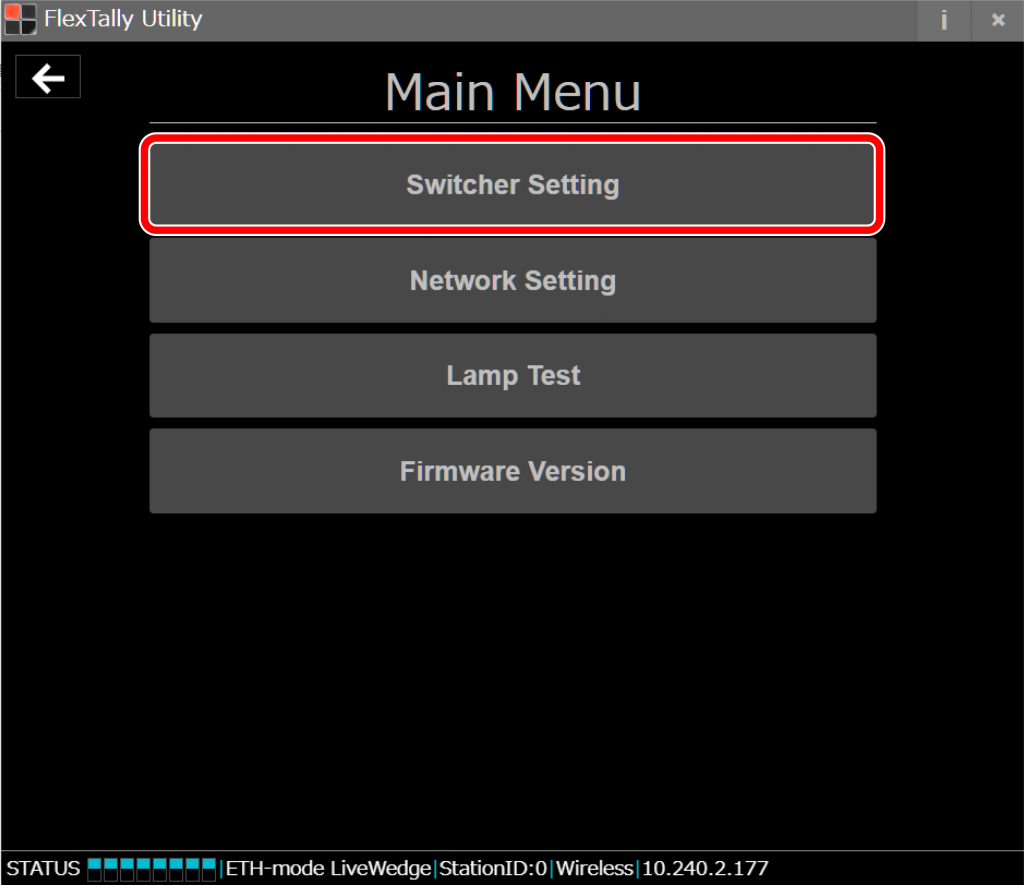
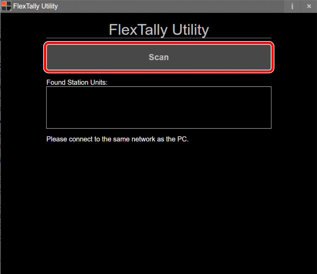
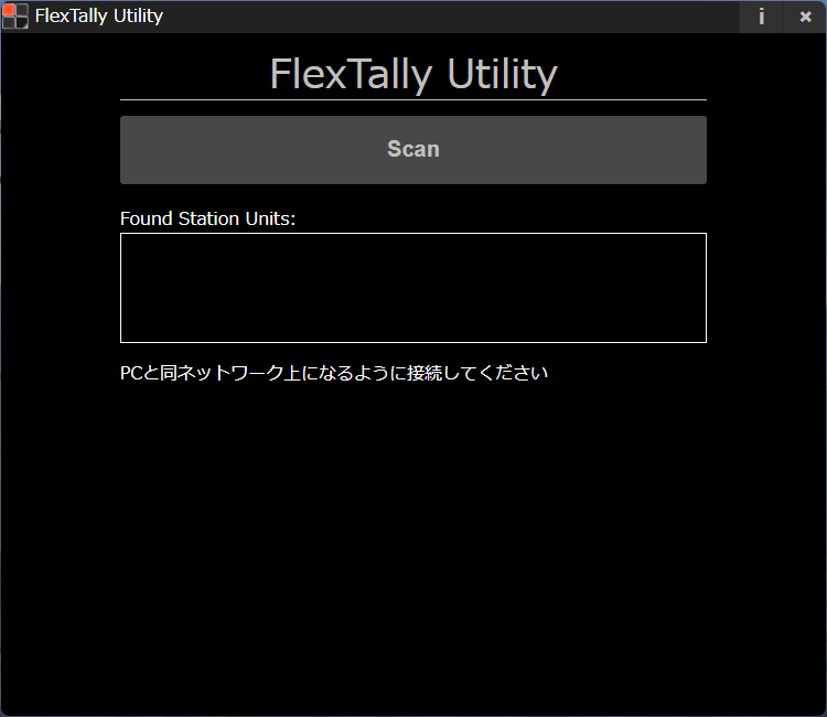
- Start FlexTally Utility. Select “Scan”.

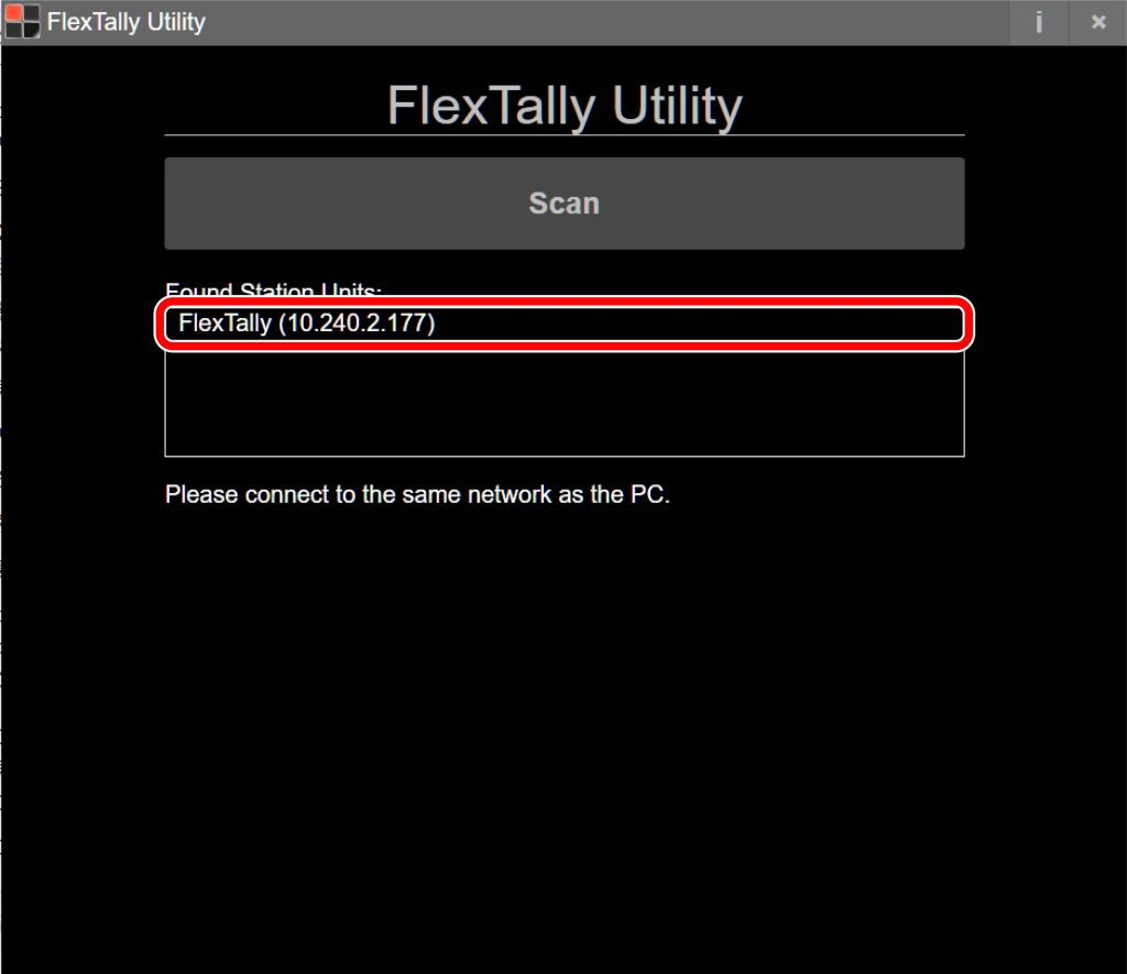
- When the Station Unit is found, the IP address of the Station Unit will be displayed. Click on the IP address.

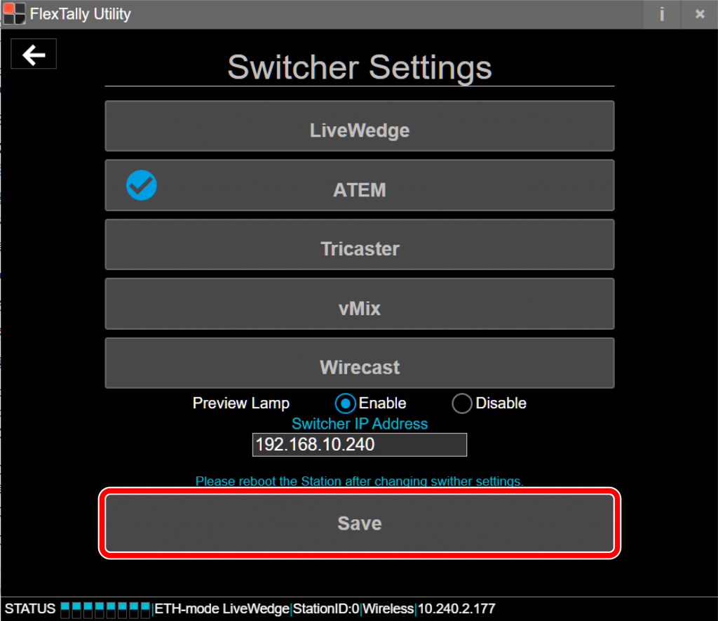
- Select “Switcher Setting”.
- Select the switcher you wish to change the setting.
- Select ON or OFF at “Preview Lamp”.
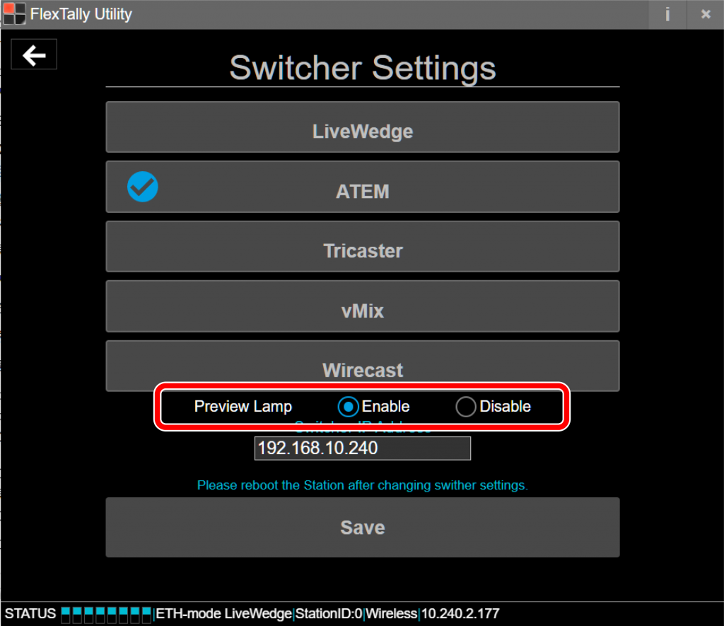
- Click on “Save”.


Connect with LiveWedge
Preparation
- Please make sure the LiveWedge firmware is Rev. 1463 or later. For details on how to update the firmware check here.
- Prepare a setting PC.
- Install “FlexTally Utility” on the setting PC. Click here for installation instructions.
- Please update the FlexTally Station Unit firmware to the latest version. See here for how to update.
- Make sure the Lamp Units are fully charged
- Connect the Station Unit and the Lamp Units. Connection methods are here.
- Turn ON the No.1 DIP switch on the Station Unit and change the connection method to Ethernet.
Setup Steps
- Set the DIP switches of each Lamp Units for 4 channels.
- Make sure the FlexTally Station Unit, LiveWedge and the setting PC are in the same network.
- Connect the AC adapter to the FlexTally Station Unit and turn on the power. The status LED lights blue when the power is turned on.
- Start FlexTally Utility and select “Scan”.
- When the Station Unit is found, the IP address will be displayed. Select the IP address.
- Select “Switcher Setting”.
- Select “LiveWedge”.
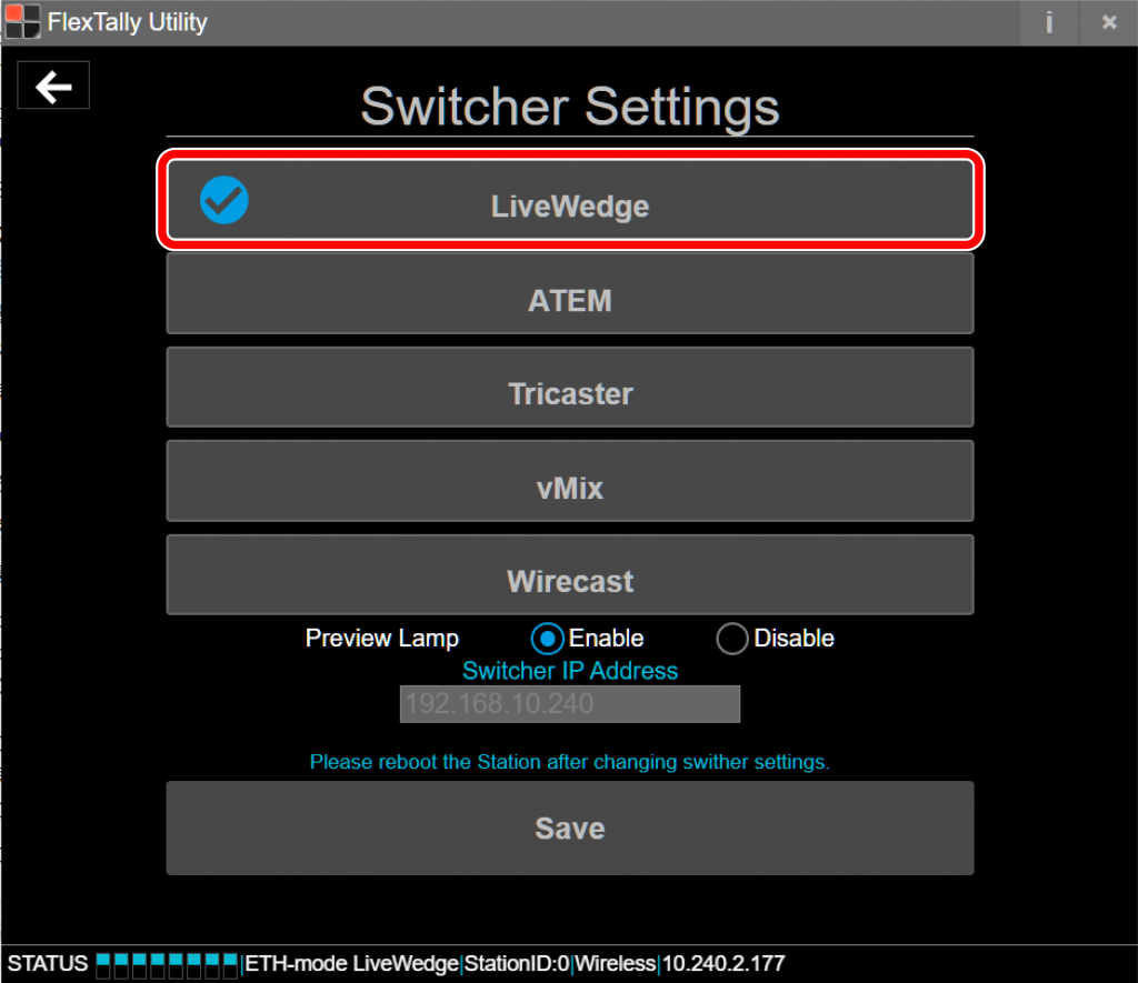
- Click “Save”.

- Press and hold the power button on the Lamp Units. When the power turns on, the status LED lights up blue.

- Switch LiveWedge’s video channels and check each the Lamp units response.


Change connection when using multiple LiveWedges
If there is more than one LiveWedge on the same network, you can switch the connection with the Function 1 button.
You can then check the connection by switching input channels on LiveWedge.
Note
- Since the “Test Lamps” option in “FlexTally Utility” is affected by the LiveWedge connection, please test when LiveWedge is not connected.
Connect with Blackmagic Design ATEM
Setup Movie
Preparation
- Prepare a PC for setting.
- Install “FlexTally Utility” on the setting PC. Click here for installation instructions.
- Please update the firmware of the FlexTally Station Unit to the latest version. See here for how to update.
- Install “ATEM Software Control” and “ATEM Setup” on the PC for setting.
- Make sure the Lamp Unit is fully charged.
- Connect the Station Unit and the Lamp Unit. Click here for how to connect.
- Set DIP switch No. 1 on the Station Unit to ON and set the connection method to “Ethernet” setting.
Setup Steps
- Set the DIP switches of each Lamp Unit for the channels to be used (please refer here for details).
- Connect the Station Unit, ATEM switcher and the setup PC to the same network.
- Connect the AC adapter to the Station Unit and turn it on. When the power turns on, the status LED lights up blue.
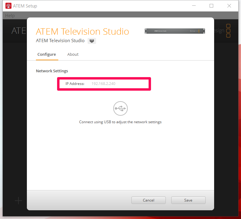
- Check the ATEM IP address from “ATEM Setup”.
- Start FlexTally Utility and select “Scan”.
- When the Station Unit is found, the IP address of the Station Unit will be displayed. Click on the IP address.
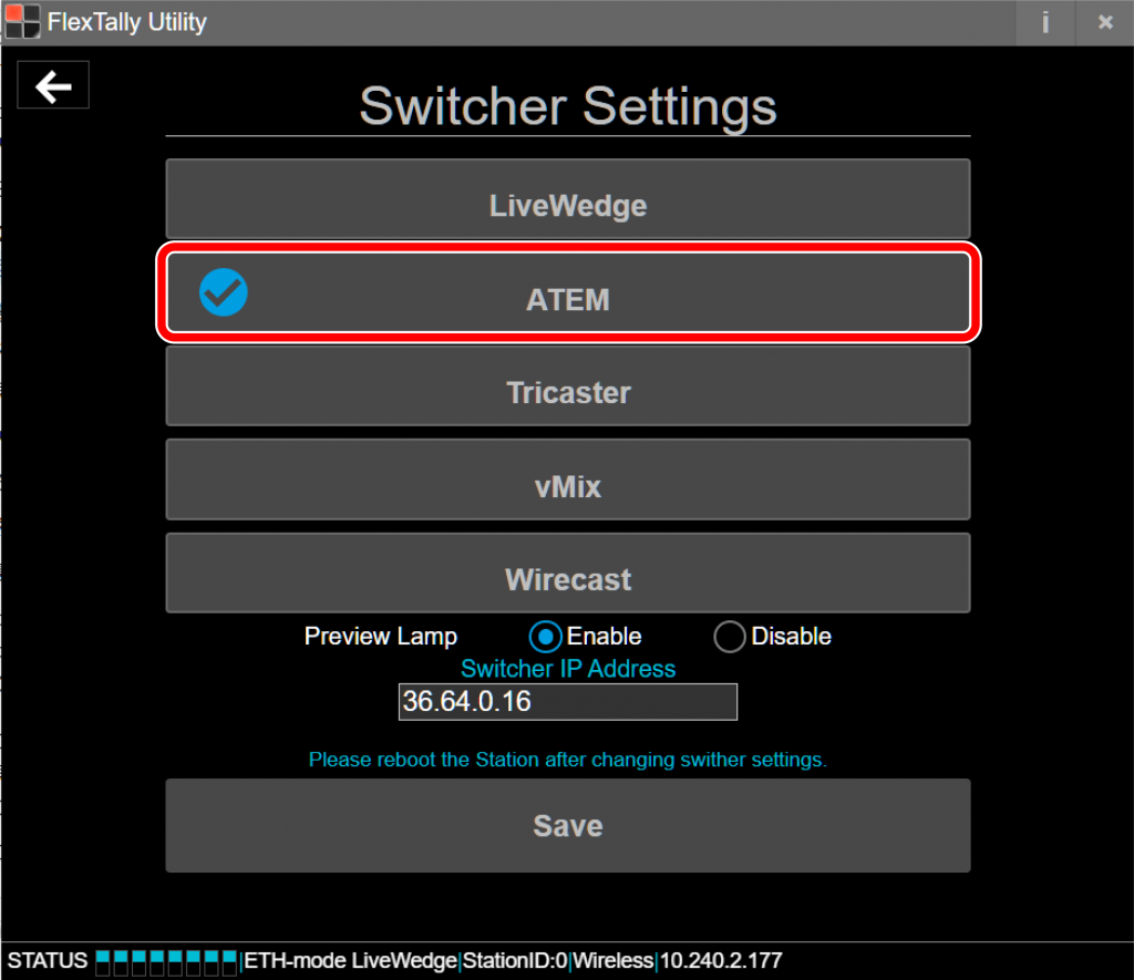
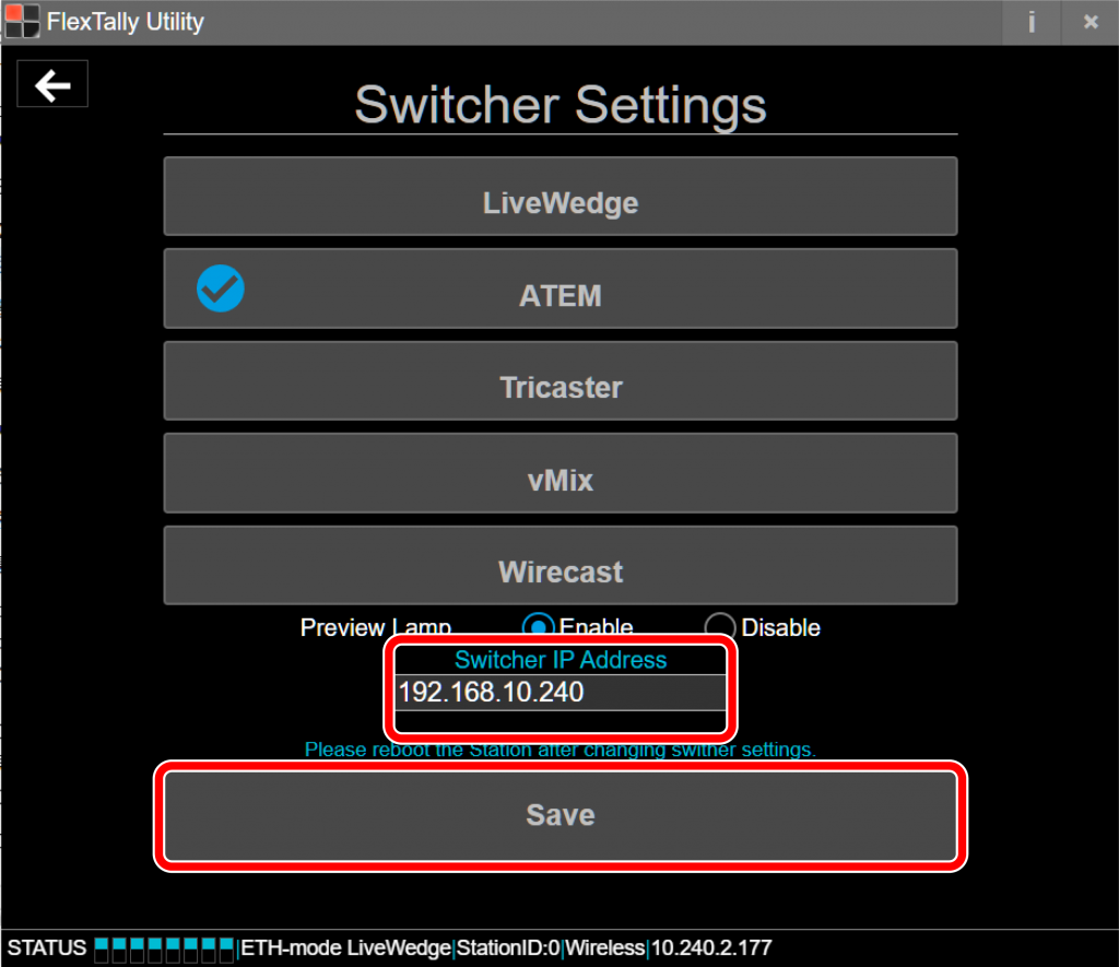
- Select “Switcher Setting”.

- Select “ATEM”.

- Enter the ATEM IP address shown at step 4 at “Switcher IP Address”. Click “Save”.
- Press and hold the power button on the Lamp Unit. When the power turns on, the status LED lights up blue.
- Switch channels on your ATEM switcher by using the “ATEM Software Control” and make sure each lamp responds.


Note
- Since the “Test Lamps” option in “FlexTally Utility” is affected by the ATEM connection, please test when ATEM is not connected.
Connect with Vizrt(NewTek) TriCaster*
Preparation
- Prepare a PC for setting.
- Install “FlexTally Utility” on the setting PC. Click here for installation instructions.
- Please update the firmware of the FlexTally Station Unit to the latest version. See here for how to update.
- Make sure the Lamp Units are fully charged.
- Connect the Station and the Lamp Units. Connection methods are here.
- Turn ON the No.1 DIP switch on the Station and change the connection method to “Ethernet”.
Setup Steps
- Set the DIP switches of each Lamp Units for the channels to be used (please refer here for details).
- Connect the Station Unit, TriCaster and setup PC to the same network.
- Connect the AC adapter to the Station Unit and turn it on. When the power turns on, the status LED lights up blue.
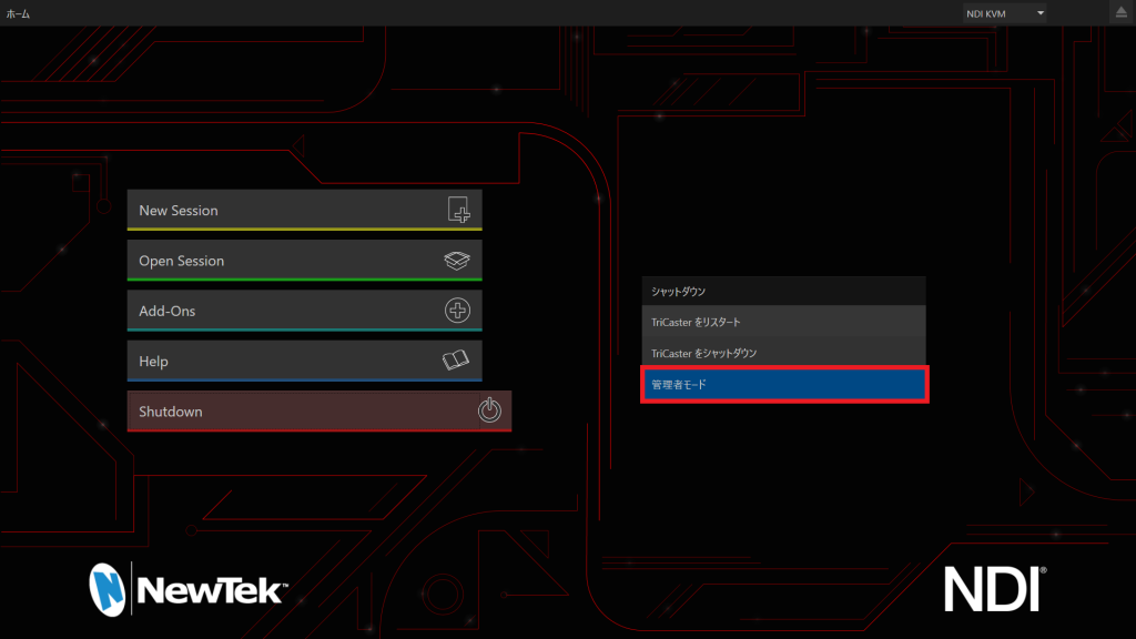
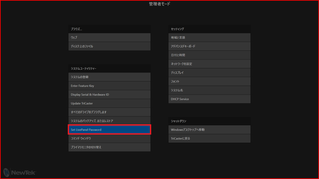
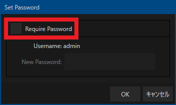
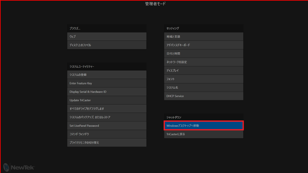
- Reset TriCaster password so that FlexTally can access TriCaster via the network. At TriCaster main page; Shutdown -> Admin mode -> Set LivePanel. Remove the check mark at Require Password. Click the OK button.
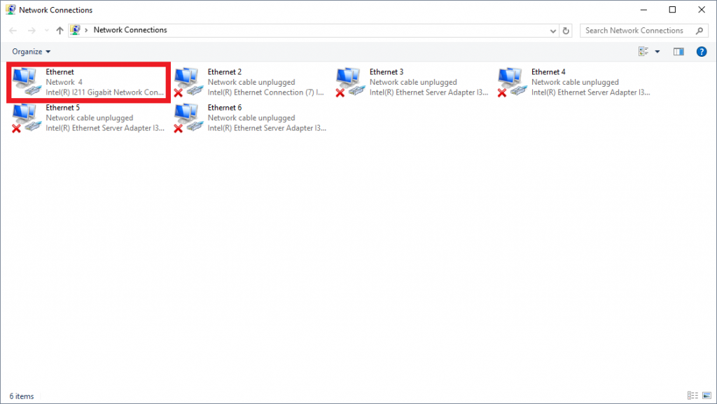
- Set TriCaster IP address. At TriCaster Admin Mode; Move Windows Desktop -> Control Panel -> Network and Internet -> Network and Sharing Center -> Change Adapter Setting -> Set the Fixed IP address from the Ethernet Property connecting to the network.
- Set FlexTally Fixed IP address. Start FlexTally Utility, select “Scan”.
- When the station Unit is found, the IP address of the Station Unit will be displayed. Click on the IP address.
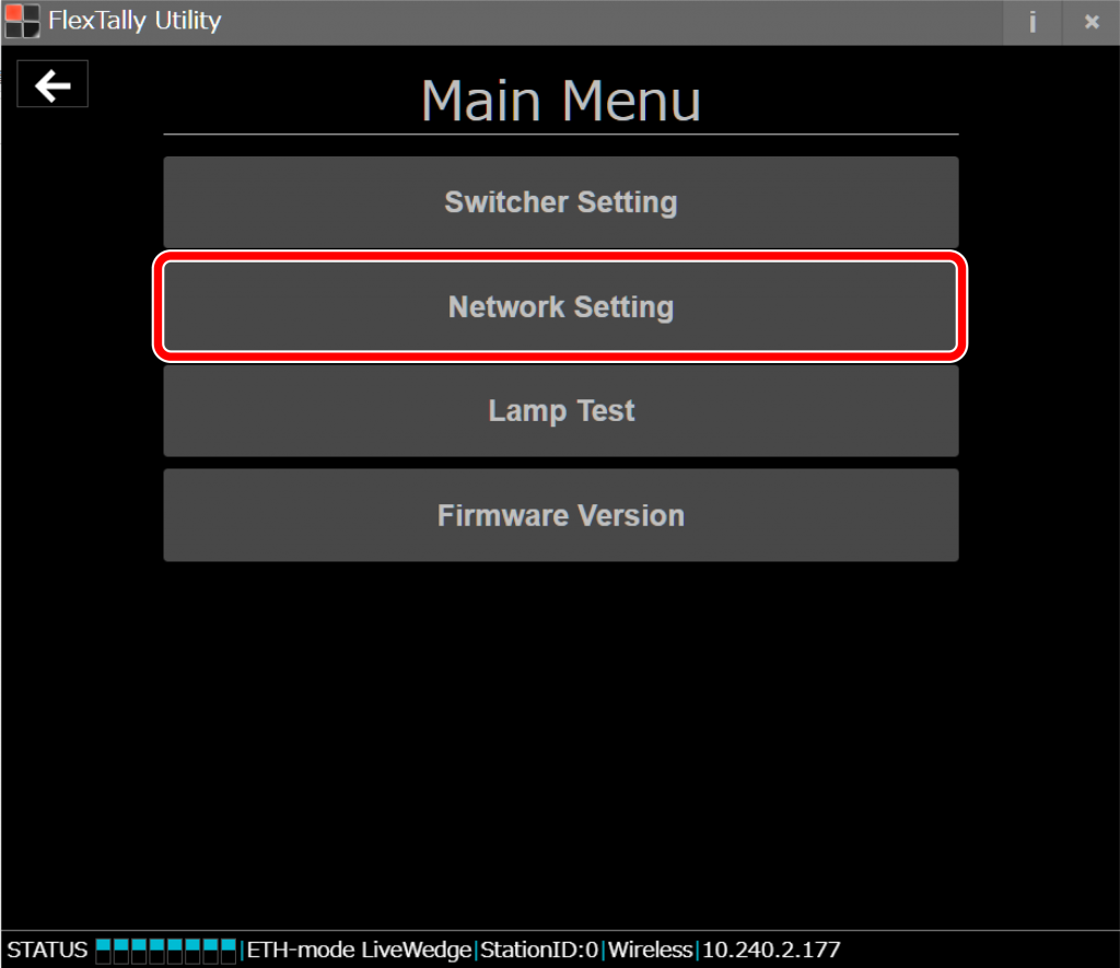
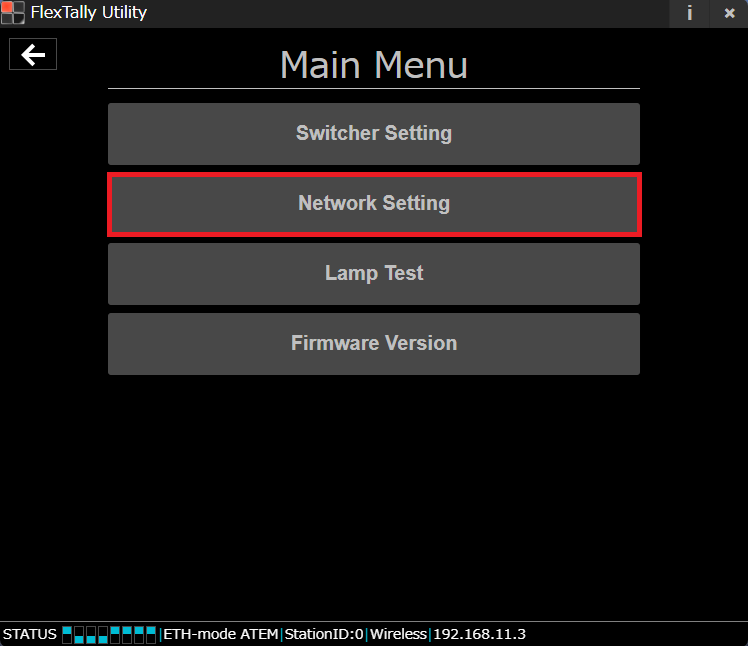
- Select “Network Setting”.
- Set the IP address of the FlexTally Station Unit so that it is in the same network as the TriCaster. Click “Save”. After setting, restart the station (by removing and reconnecting the USB power supply).
- After restarting the Station Unit, select “Switcher Setting”.
- Select “TriCaster”
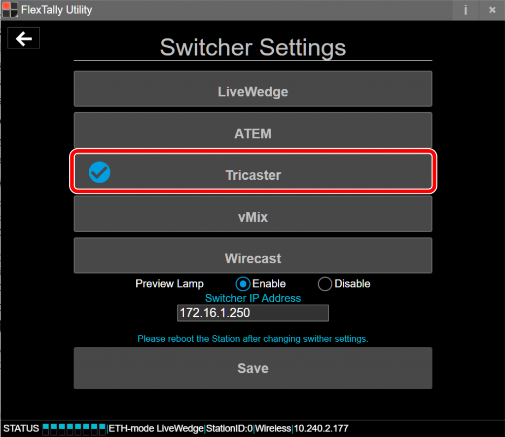
- Enter the IP address of the TriCaster and click “Save”.

- Press and hold the power button on the Lamp Unit. When the power turns on, the status LED lights up blue.
- Switch channels using TriCaster and check each the Lamp Units response.


Note
- Since the “Test Lamps” option in “FlexTally Utility” is affected by the TriCaster connection, please test when TriCaster is not connected.
Connect with vMix{#ConnectwithvMix}
Preparation
- Install vMix on your PC.
- Prepare a setting PC. There is no problem if this is the same PC as the one on which vMix is installed.
- Install “FlexTally Utility” on the setting PC. Click here for installation instructions.
- Please update the FlexTally Station Unit firmware to the latest version. See here for how to update.
- Make sure the Lamp Units are fully charged.
- Connect the Station Unit and the Lamp Units. Connection procedures are explained here.
- Turn ON the No.1 DIP switch on the Station Unit and change the connection method to Ethernet.
Setup Steps
- Set the DIP switches of each Lamp Units to match the number of channels you want to use (please refer here for details).
- Make sure the FlexTally Station Unit, the PC which vMix is installed and the setting PC are in the same network.
- Connect the AC adapter to the Station Unit and turn it on. When the power turns on, the status LED lights up blue.
- Start vMix and select “Setting”.
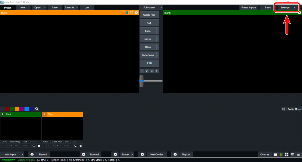
- Select “Web Controller” and find vMIX IP Address.

- Start FlexTally Utility and select “Scan”.
- When the station Unit is found, the IP address of the Station Unit will be displayed. Click on the IP address.
- Select “Switcher Setting”.
- Select “vMix”.

- Enter the vMix IP address at Step 5 at “Switcher IP Address” and click “Save”.

- Press and hold the power button on the Lamp Units. When the power turns on, the status LED lights up blue.
- Switch channels using vMix and check each the Lamp units response.


Note
- Since the “Test Lamps” option in “FlexTally Utility” is affected by the vMix connection, please test when vMix is not connected.
Connecting to Wirecast
Preperation
- Install Wirecast on your PC.
- Prepare a setting PC. There is no problem if this is the same PC as the one on which Wirecast is installed.
- Install “FlexTally Utility” and “FlexTally For Wirecast” on the setting PC. Click here for installation instructions.
*As of May 2023, only the FlexTally Utility for Windows supports Wirecast.If you use Wirecast, please use a Windows PC for the setting PC. - Please update the FlexTally Station Unit firmware to the latest version. See here for how to update.
- Make sure the Lamp Units are fully charged.
- Connect the Station Unit and the Lamp Units . Connection procedures are explained here.
- Please make sure the Station Unit and the the Lamp Units are connected correctly. Click here for connection instructions.
- Turn ON DIP switch No.1 of the Station Unit to set the connection method to Ethernet.
Setup Steps
- Set the DIP switch on the back of each lamp to the channel you want to use. Click here for setup instructions.
- Make sure the FlexTally Station Unit, the PC which Wirecast is installed and the setting PC are in the same network.
- Connect the AC adapter to the Station Unit and turn it on. When the power turns on, the status LED lights up blue.
- Start Wirecast before starting FlexTally Utility.
- Start the FlexTally Utility software and select “Scan”.
- When the Station Unit is found, the IP address will be displayed. Select the IP address.
- Select “Switcher Setting”.
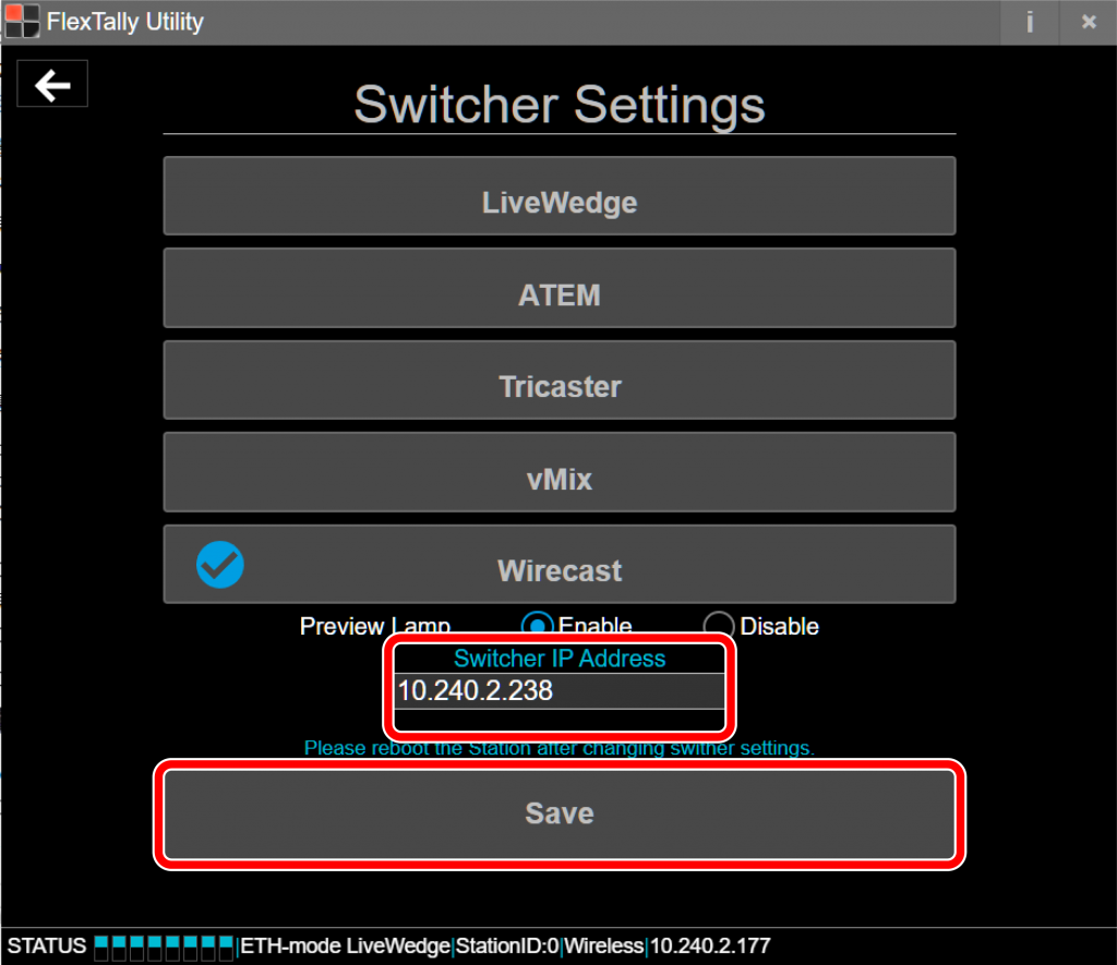
- Select “Wirecast”.

- At “Switcher IP Address”, enter the IP address of the PC which is Wirecast. Click “Save”.
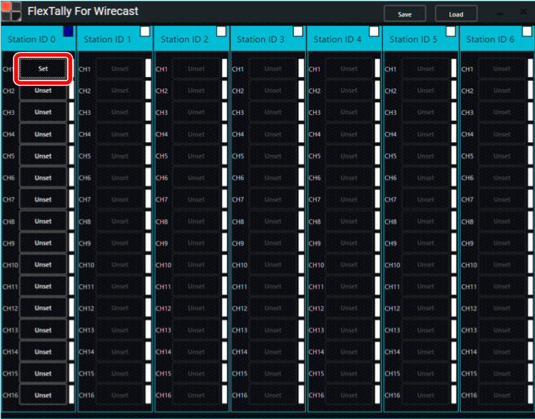
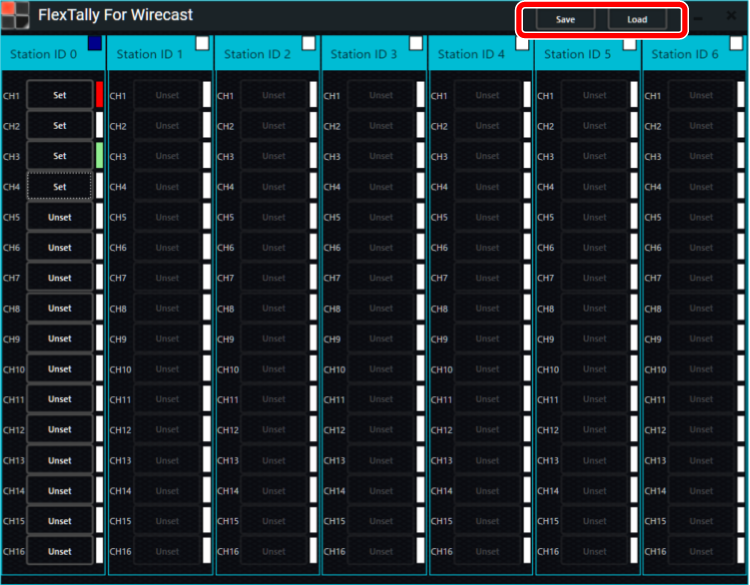
- Next, set up the Lamp Units. Start “FlexTally For Wirecast” and select “Unset” for the Lamp Units you wish to setup.
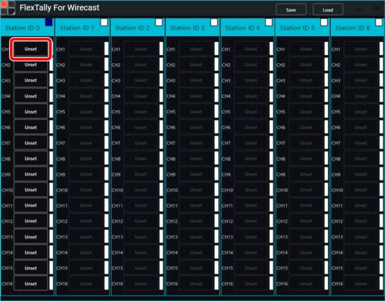
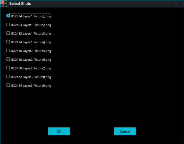
- When “Select Shots” starts, select the shot you wish to set for the Lamp Units and click “OK”. Here, as an example, we set Layer:1 Picture1.png for CH1 with Station ID 0.
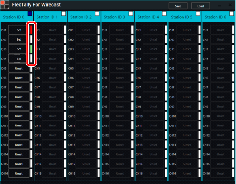
- “Unset” will change to “Set” if the Lamp Units setup is completed correctly. Set other lamps in the same way.
- Press and hold the power button on the Lamp Units. When the power turns on, the status LED lights up blue.
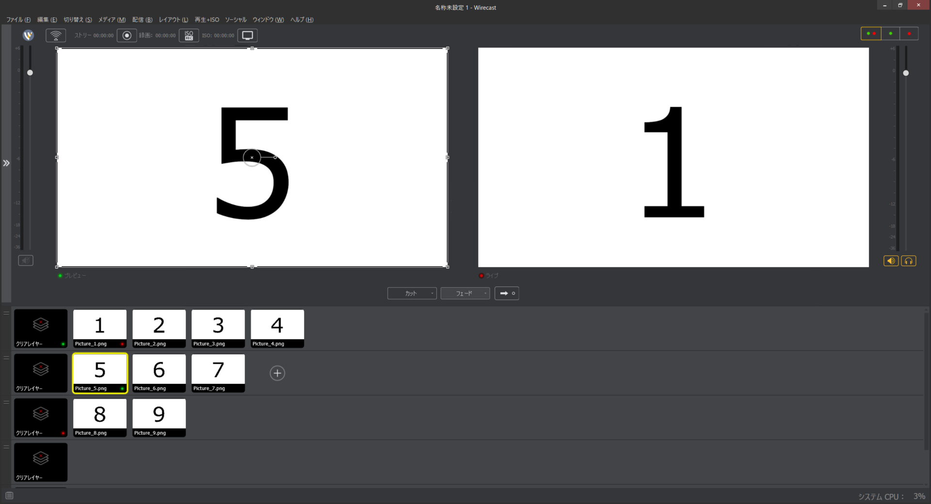
- After completing the settings, use Wirecast to select transitions and previews, and check if the Lamps light up. If the settings are correct, the Lamp Units color notation on “FlexTally For Wirecast” will also light up in red or green accordingly.
- To save the Lamp Unit settings, click “Save” in “FlexTally For Wirecast”. To load saved settings, click “Load” to load the settings file.


Troubleshooting
- I get an error and cannot update the Station Unit firmware. → Please start FlexTally Utility as an Administrator.
- I am unable to connect to the station unit.→ Please change the setting to fixed IP instead of DHCP. Click here for configuration instructions.
- I can’t set the lamp in FlexTally For Wirecast.→ Please check that the IP address you entered in “Switcher IP Address” in FlexTally Utility is correct.
Note
- Since the “Test Lamps” option in “FlexTally Utility” is affected by the Wirecast connection, please test when Wirecast is not connected.
4.Connect with GPIO Tally Output Switcher
GPIO Information of FlexTally
FlexTally can be connected to switchers with tally ports.
Prepare a cable to connect with FlexTally according to the GPIO specification of each switcher.
GPIO Information of each Switcher
Confirmed switcher and Station GPIO type information is listed here.
FlexTally GPIO Information
Dsub 15pins Mini Female
| Pin | Station |
|---|---|
| 1 | GND |
| 2 | GPIO-1 Red |
| 3 | GPIO-2 Red |
| 4 | GPIO-3 Red |
| 5 | GPIO-4 Red |
| 6 | RSVD |
| 7 | GPIO-5 Red or 1 Green(*) |
| 8 | GPIO-6 Red or 2 Green(*) |
| 9 | GPIO-7 Red or 3 Green(*) |
| 10 | GPIO-8 Red or 4 Green(*) |
| 11 | RSVD |
| 12 | RSVD |
| 13 | GND |
| 14 | GND |
| 15 | GND |
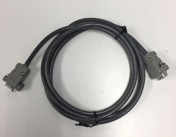
Example GPIO Cable
GPIO Information for Switchers
Switcher Compatability by Manufacturer
Confirmed compatible switcher list (as of Jan 2022).
| Manufacturer | Switcher | DIP 1 | DIP 2 | DIP 3 | DIP 4 |
|---|---|---|---|---|---|
| Roland | VR-4HD | OFF | ON | ON or OFF | ON |
| Roland | VR-120HD | OFF | ON | ON or OFF | ON |
| Roland | V-160HD | OFF | ON | ON or OFF | ON |
| Roland | VR-1HD | OFF | OFF | OFF | ON |
| SONY | MCX-500 | OFF | ON | ON or OFF | ON |
| Panasonic | AG-HMX100 | OFF | ON | OFF | ON |
| Panasonic | AW-HS50 | OFF | ON | OFF | ON |
| Vizrt(NewTek)(GPIO connected) | Tricaster460 Tricaster TC1 | OFF | OFF | OFF | ON |
| DataVideo | SE-1200MU | OFF | ON | 4ch preview availability(ON)6ch preview not availability(OFF) | ON |
| Blackmagic Design (GPIO connecte) | GPI and Tally Interface | OFF | ON | OFF*1 | ON |
*Only Program is supported when connected Blackmagic Design.
See this page about detail of FlexTally’s DIPs
Station GPIO input circuit diagram
GPIO Type1
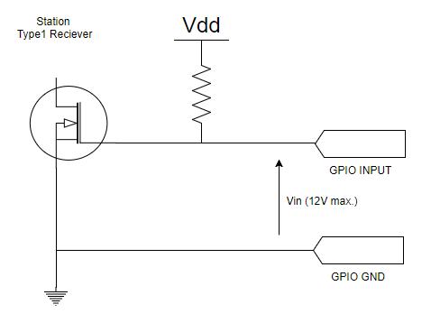
| Vin | Polarity (DIP3) Normal | Polarity (DIP3) Reversed |
|---|---|---|
| Short | Lamp ON | Lamp OFF |
| Open | Lamp OFF | Lamp OFF |
GPIO Type2
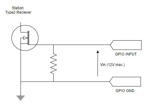
| Vin | Polarity (DIP3) Normal | Polarity (DIP3) Reversed |
|---|---|---|
| 0V or Open | Lamp ON | Lamp OFF |
| 3~12V | Lamp OFF | Lamp ON |
Connecting to a GPIO Switcher
Setup Movie
Preparation
- Make sure the Lamps are fully charged.
- Connect the Station and Lamps. Connection methods are here.
Setup Steps
- Set the DIP switches of each Lamp for the channels to be used (please refer to here).
- Please turn off the number 1 on the Station’s DIP switch to change the connection method to GPIO.
- Set DIP switches No.2, 3, and 4 on the Station according to the purpose of the switcher (please refer here for details).
- Connect the Station and switcher with a GPIO cable.
- Press and hold the power button on the lamp. When the power turns on, the status LED lights up blue.
- Connect the AC adapter to the station and turn it on. When the power turns on, the status LED lights up blue.
- Switch the channel of the switcher and check that each lamp reacts.
Note
- Since the “Test Lamps” option in “FlexTally Utility” is affected by the switcher connection, please test when a switcher is not connected.
5.Other Functions
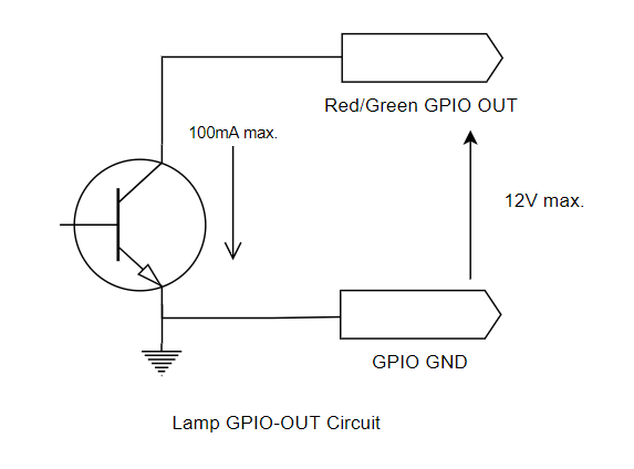
Lamp GPIO Output
You can connect* to external equipment such as a field monitor with a corresponding Tally GPIO input. The output tally signal is synchronized with the lighting state of the connected Lamp.
*Separate cable required.
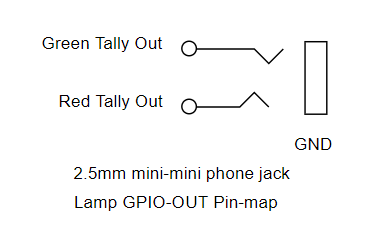
Lamp GPIO-OUT pin map
Stereo mini (2.5 mmΦ) plug.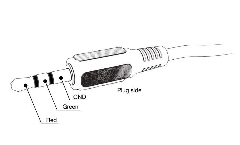
Lamp GPIO-OUT schematic
Wired Connection Between Station and Lamp
If the distance between the Station and the Lamp is too far, or if the local radio wave environment is not suitable for a wireless conenction, we recommend using FlexTally with a wired connection.
*Wired connection cables must be purchased separately.
Cable Type
Please prepare a 2-core pair cable.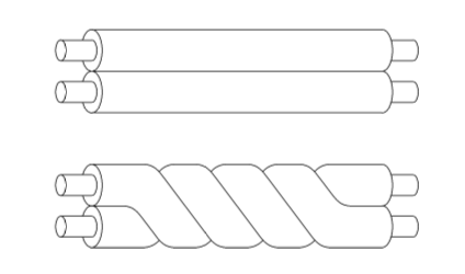
Connection Steps
Connect P and P and N and N of the WIRE port of each Station and Lamp.
Multiple Lamps can be connected as follows.*1
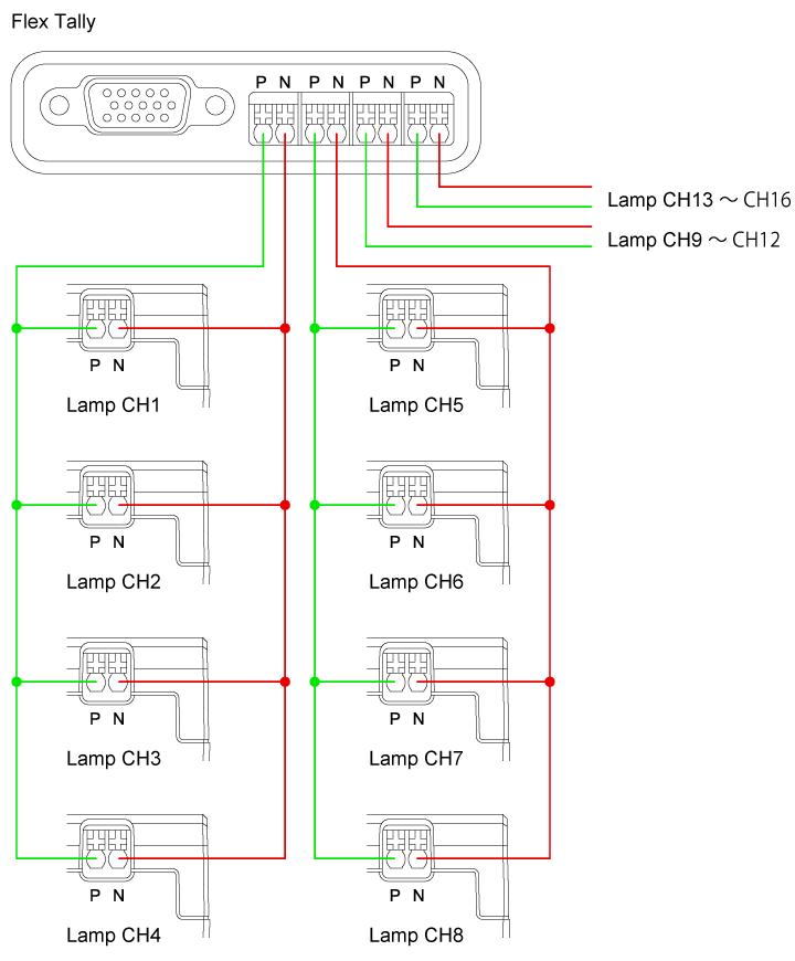
*The same signal is output from all four wired ports of the Station.
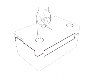
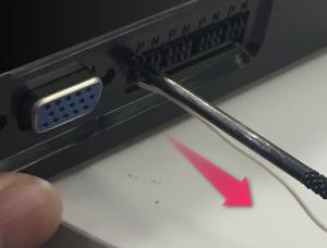
Insert/Remove Cable
How to insert
Insert the cable while pushing the cross part of the port.
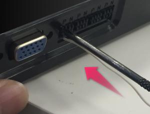
How to Remove
While holding down the cross part of the port, disconnect the cable.
Set DIP Switch
Make sure DIP switch No.8 is set to OFF and set the Station and lLaamp to wired mode.*2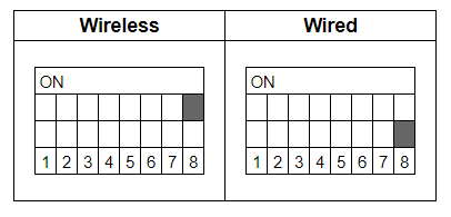
Note
*1 For wired connections, connection distance and number of connectable Lamps may change depending on factors such as wiring distance, wire material, number of Lamps, environment, etc. Please test before using in a critical location.
*2 It is not possible to use a mixture of wireless and wired connections with multiple Lamps.
Lamp Illumination Test
FlexTally Utility has a Lamp Test function available, should you need to troubleshoot any Lamp illumination issues.
Preparation
- Prepare a PC for setting.
- Install “FlexTally Utility” on the setting PC. Click here for installation instructions.
- Please update the firmware of the FlexTally Station Unit to the latest version. See here for how to update.
- Make sure the lamp Unit is fully charged.
- Connect the Station Unit and the lamp Unit. Click here for how to connect.
- Set DIP switch No. 1 on the Station Unit to ON and set the connection method to “Ethernet” setting.
Setup Steps
- Set the DIP switches of each Lamp Unit for the channels to be used (please refer here for details).
- Connect the Station Unit and the setup PC to the same network.
- Connect the AC adapter to the Station Unit and turn it on. When the power turns on, the status LED lights up blue.
- Press and hold the power button on the Lamp Unit. When the power turns on, the status LED lights up blue.
- Start FlexTally Utility. Select “Scan”.
- When the Station Unit is found, the IP address of the Station Unit will be displayed. Click on the IP address.
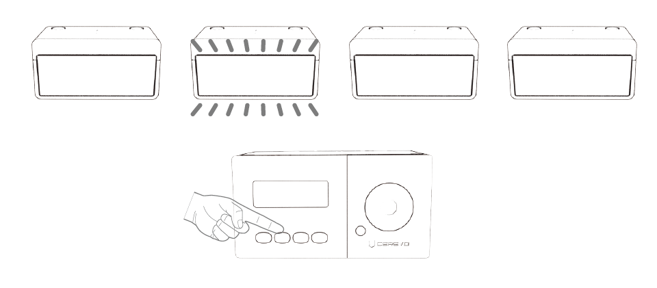
- Select “Test Lamp”.

- Click the number buttons to see if the corresponding the Lamp Units illuminate.
To set the channel numbers for each Lamp Units, please check here. The Lamp Unit lights red when “PGM” is selected, and green when “PVW” is selected.
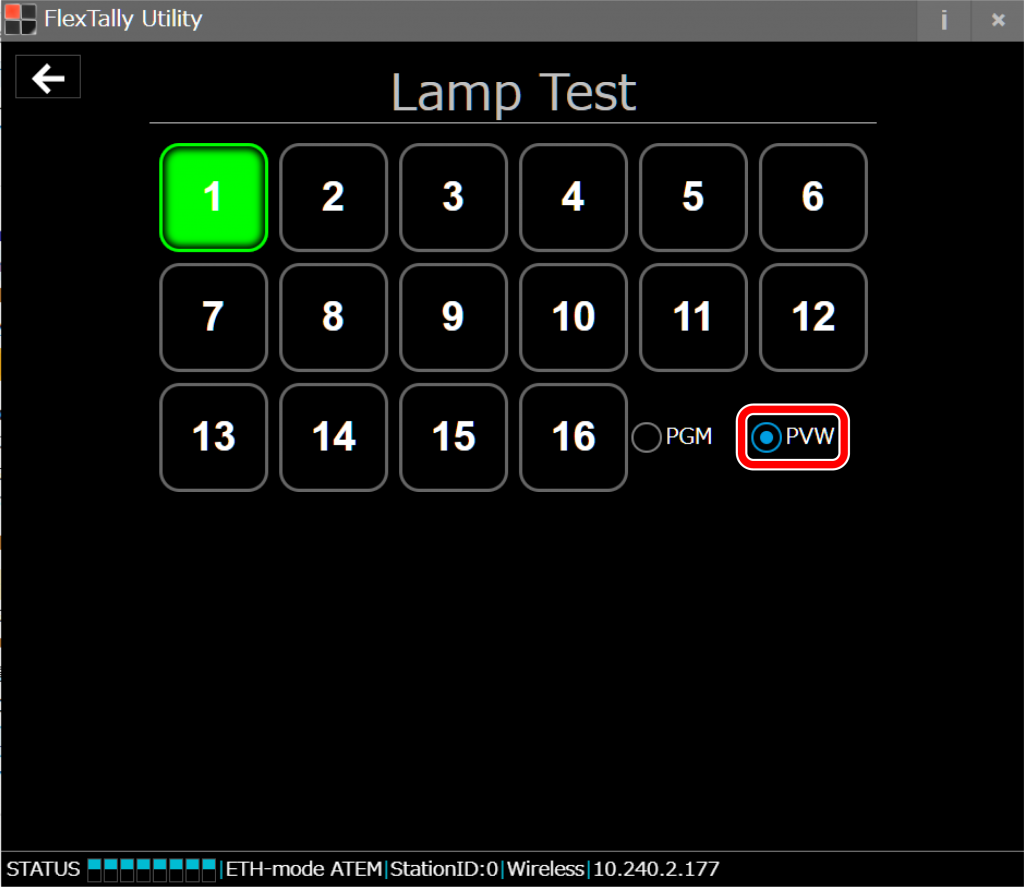


Note
- “Lamp Test” does not work when an Ethernet switcher is connected within the same network, or when the connection method of the FlexTally Station Unit is set to “GPIO” setting.
IP address settings
Open the FlexTally Utility application and set the station IP address for DHCP or fixed IP.
*The initial setting is DHCP.
* When connecting the station and Cerevo LiveWedge directly with a LAN cable, click DHCP. (Auto IP will be used)
– Connect to the station.
Place the station and the PC using the FlexTally Utility application on the same network and plug the USB power cable into the station. Search for the station in FlexTally Utility application.
Click found IP address.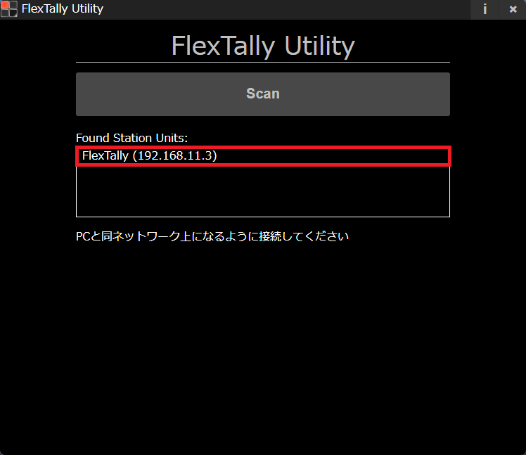
– Select Network Setting
– When setting to DHCP
Click DHCP and Save.
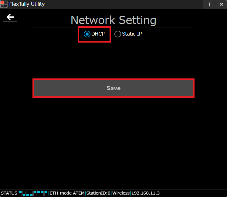
After setting, unplug the AC adapter to reboot the station.
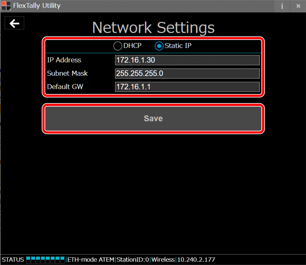
– When setting to a fixed IP
Click fixed IP.
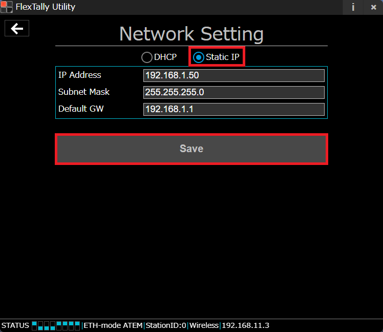
Input the IP address, subnet mask and default gateway, and then click save.
After setting, unplug the AC adapter to reboot the station.
*If you accidentally set an IP address that is not on the same network, the station unit will not be found. In order to delete the incorrect IP address, initialize the station unit.
6.Initialization
Initialization
Station
- Confirm that the USB power supply is not connected.
- Press the Function 1 Button and the Function 2 Button simultaneously.
- Hold the buttons and connect the USB power supply.
- Hold the buttons simultaneously for 10 seconds.
Settings other than the DIP switch will be reset.
Lamp
As of December 2017, there is no initialization function.
7.Updates
History
FlexTally Utility (Windows application)
*Please refer here for how to update.
- ver 2.0.0 (2023/5/31)
- Improved connection stability during wireless connection
- Partial UI change
- ver 1.2.1 (2022/2/1)
- Fixed minor bugs
- ver 1.2.0 (2022/1/24)
- Supported Wirecast
- Supports preview lamp lighting ON / OFF selection
- ver 1.1.0 (2019.07.23)
- Supported vMix
- Added function to update Station firmware and Lamp firmware.
- Fixed minor bugs
FlexTally Utility MacOS application
*Please refer here for how to update.
- ver 2.0.0 (2023/5/31)
- MacOS version release
Station firmware
* Please refer here for how to update.
- Rev. 0031 (2023/5/31)
- Improved connection stability during wireless connection
- Supported FlexTally Utility MacOS version
- Rev. 0030 (2022/2/1)
- Fixed minor bugs
- Rev. 0029 (2022/1/24)
- Supported Wirecast
- Supports preview lamp lighting ON / OFF selection
- Rev.0025 (2019.07.23)
- Supported vMix
Lamp firmware
As of May 2023, there is no updates on FlexTally Lamp Unit firmware.
How to update station firmware
This page explains how to update the FlexTally Station Unit firmware. Please see here for the latest firmware version and revision history.
Preperation
- Prepare a PC for setting.
- Install the latest version of “FlexTally Utility” on the setting PC. Click here for installation instructions.
- Set DIP switch No. 1 on the Station Unit to ON and set the connection method to “Ethernet” setting.
Setup Steps
- Connect the Station Unit and the setup PC to the same network.
- Connect the AC adapter to the Station Unit and turn it on. When the power turns on, the status LED lights up blue.
- Start FlexTally Utility and select “Scan”.
- When the Station Unit is found, the IP address of the Station Unit will be displayed. Click on the IP address.
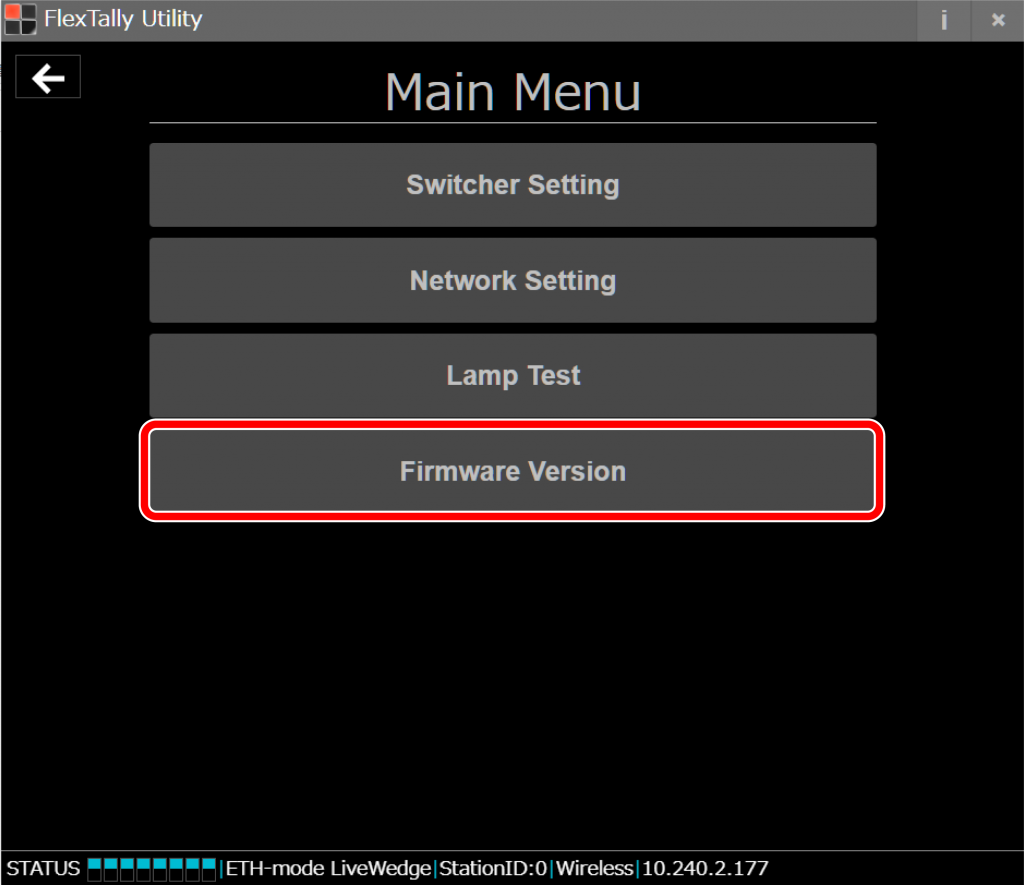
- Select “Firmware Version”.
- Select “Update Station Unit”.
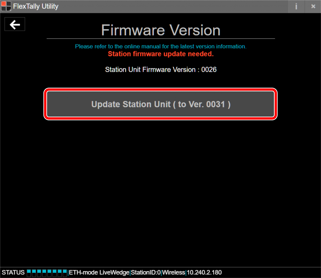
If “Update Station Unit” is gray-colored, the latest firmware is already installed. No update is required.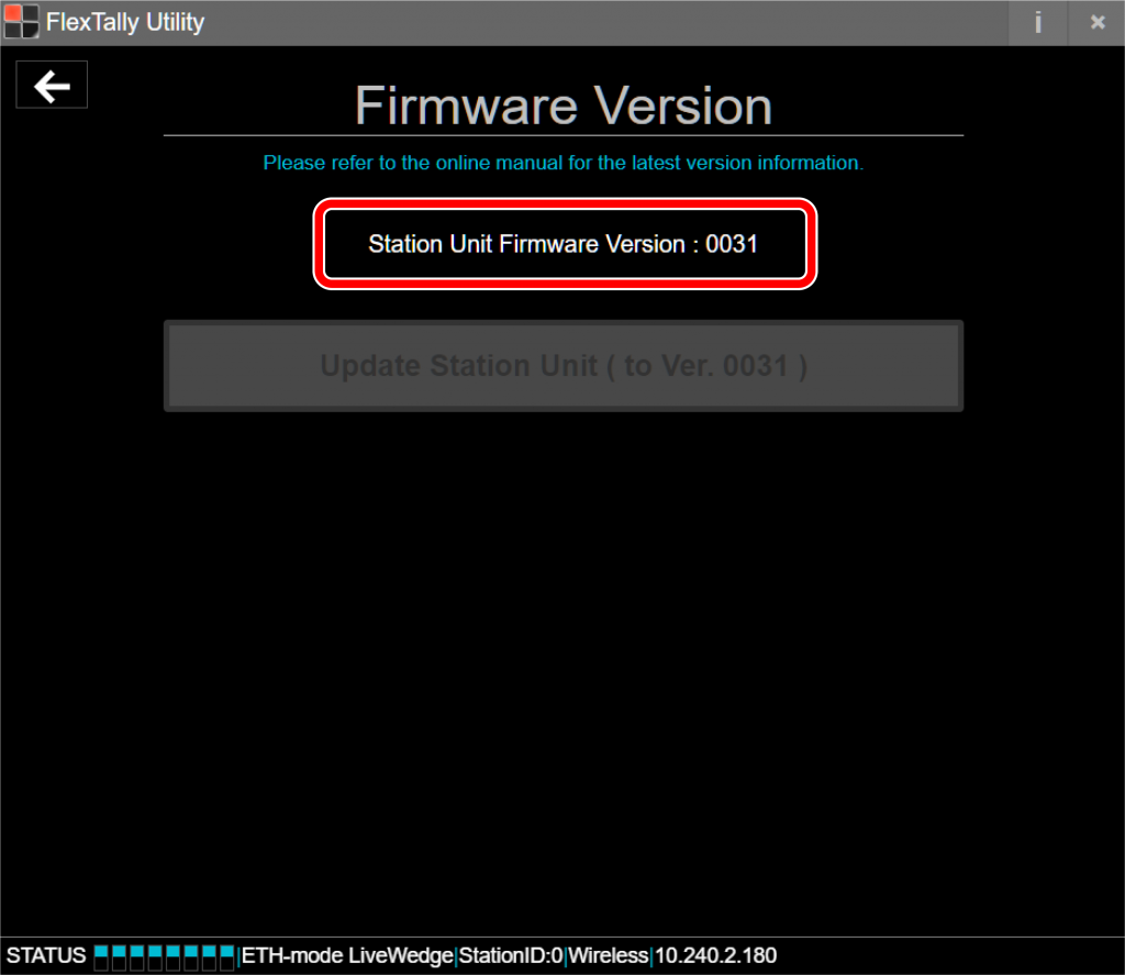
- The update will start, so please wait until the update is completed.
Do not turn off the power of the FlexTally Station Unit. Do not disconnect the network connection during the update. Click “OK” when the update is complete.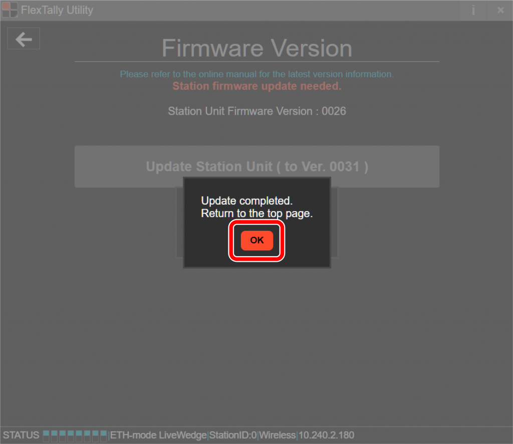


How to update FlexTallyUtility (application)
When updating FlexTallyUtility from a previous version, first uninstall FlexTallyUtility from the setting PC. After that, download the latest version of FlexTallyUtility from here and install the latest version of the application on the setting PC.
8.Q&A
Compatible Switchers
| Manufacturer | Switcher | Connection |
|---|---|---|
| Cerevo | LiveWedge | Ethernet |
| Blackmagic Design | ATEM Mini ATEM Mini Pro ATEM Mini Pro ISO ATEM Mini Extreme ATEM Mini Extreme ISO ATEM SDI ATEM SDI Pro ISO ATEM SDI Extreme ISO ATEM Television Studio ATEM Television Studio HD ATEM Television Studio Pro HD ATEM Television Studio Pro 4K ATEM Television Studio HD8 ATEM Television Studio HD8 ISO ATEM Production Studio 4K ATEM 1M/E Production Studio 4K ATEM 2M/E Production Studio 4K ATEM 4M/E Broadcast Studio 4K ATEM 1 M/E Constellation HD ATEM 2 M/E Constellation HD ATEM 4 M/E Constellation HD ATEM Constellation 8K | Ethernet |
| GPI and Tally Interface | GPIO*(GPIO Cable for Cerevo’s FlexTally) | |
| Vizrt(NewTek) | TriCaster 1 Pro TriCaster 2 Elite TriCaster TC1 TriCaster TC410 Plus TriCaster Mini X TriCaster Mini 4K TriCaster Mini Advanced R2 TriCaster Mini AE2 TriCaster Mini AE3 TriCaster 410 TriCaster 460 | Ethernet |
| Roland | V-60HD V-160HD V-800HD V-800HD MK-2 V-1200HD V-1600HD V-600UHD VR-6HD VR-120HD | GPIO*(GPIO Cable for Cerevo’s FlexTally) |
| V-1HD+ VR-4HD | GPIO Cable for Cerevo’s FlexTally | |
| VR-1HD V-1HD V-1SDI V-8HD * PST (Preset) output is not supported. | USB-GPIO Converter for FlexTally | |
| SONY | MCX-500 | GPIO*(GPIO Cable for Cerevo’s FlexTally) |
| Vizrt(NewTek) | TriCaster 1 Pro TriCaster 2 Elite TriCaster TC1 TriCaster 410 TriCaster 460 | GPIO*(GPIO Cable for Cerevo’s FlexTally) |
| Panasonic | AG-HMX100 AW-HS50 | GPIO*(GPIO Cable for Cerevo’s FlexTally) |
| DataVideo | SE-1200MU SE-3200 HS-1300 HS-3200 | GPIO*(GPIO Cable for Cerevo’s FlexTally) |
| StudioCoast PTY LTD | vMix | Software |
| Telestream | Wirecast | Software (Ethernet) |
| Lumantek | ez-Pro VS4 | USB-GPIO converter for FlexTally |
| FOR-A | HVS-100/110 | GPIO*(GPIO Cable for Cerevo’s FlexTally) |
Updated 2024 October
Frequently Asked Questions
General Inquiries
- What size is FlexTally?
- What items are included?
- How long is the charging time?
- How long does FlexTally work via battery power?
- What regulatory rules does FlexTally comply with?
- Any firmware updates in future?We have ended firmware updates for FlexTally.
About FlexTally Unit
- Can I charge the battery or use a mobile battery?FlexTally can be charged with a 5V/1.5A AC adapter. You can also use a mobile battery which follows those specifications. Please note, Cerevo does not guarantee operation with 3rd party mobile batteries. Any accident caused by a non Cerevo product is not covered by FlexTally’s warranty.
- Can I use a cable other than the included USB cable?You can use a USB cable other than the one included in the box. Please note, Cerevo does not guarantee operation with 3rd party USB cables. Any accident caused by a non Cerevo product is not covered by FlexTally’s warranty.
- About LED status.
- How to initialize FlexTally.
About FlexTally Utility
About Switchers
- Are there switchers that have been tested with FlexTally?
- Cannot connect with tested switcher.
Cerevo has officially confirmed some switchers are compatible with FlexTally.
See this page to find the list of tested switchers.However you may not connect with a switcher on the list when your firmware is not up-to-date. Please check if your firmware is up-to-date when you cannot connect with your switcher. If not, update your firmware and try again to connect with the switcher.
See this page to find steps to update firmware. - What kind of switcher can be used?
- What are FlexTally’s GPIO out specifications?
FlexTally Troubleshooting
- Cannot find the station using the FlexTally utility application
- Is there any way to check if a switcher is connected properly?
- Lamps do not illuminate when using ATEM switchers
- Lamps do not illuminate when using TriCaster switchers
- Lamps do not illuminate green
- Lamps do not illuminate or illuminate incorrectly
- IP address settings
- Cannot Use FlexTally with Tricaster Advanced Edition 3 Software
- Lamp Illumination Test
Cannot find the station using the FlexTally utility application
Connect using DHCP to complete setup.
* When a Fixed IP connection is required, follow the same steps below to connect to the station initially. After that, change the settings to use a fixed IP.
1. Set the station to DHCP
Initialize the station (Initialization instructions)
2. Set PC to DHCP
a: In Windows 10: Go to “Start Menu” > “Settings” > “Network & Internet” > “Ethernet” > “Network and Sharing Center” > “Change adapter settings”.
b: Select the currently being used Ethernet adapter, right click and select “Properties”.
c: Double click Internet Protocol Version 4 (TCP/IPv4)
d: Select “Obtain an IP address automatically” and click OK.
*When a fixed IP address is required, after setup is complete, return to this point and change to “Use the following IP address”, then enter as required.
3. Connect directly with a LAN cable.
a: After the station and PC are set to DHCP, connect them directly using a LAN cable. (Turn off Wi-Fi if necessary)
b: Unplug the AC adapter to reboot the station.
c: Start the application and search for the station (the station will appear with an IP address starting 169.254.x.x).
Is there any way to check if a switcher is connected properly?
Check if the Tally LED on the station illuminates red or green when switching. (LED location – Product overview)
Switcher channels 1-8 illuminate red (program) and green (preview). Channels 9-16 illuminate pink (program) and light green (preview).
*When using switchers without a preview output, the LED will not illuminate green or light green.
When the Tally LED does not illuminate at all, please check the connection between the station and the switcher.
Lamps do not illuminate when using ATEM switchers
Refer to Connect with Blackmagic Design ATEM to set up. In Setup step 6, if you cannot find the IP address of the station, check “Cannot find the station in FlexTally utility application.” If you were able to finish all setup steps but the lamps do not illuminate at all, see the following troubleshooting steps.
- Is the ATEM switcher and station is connected via LAN directly or via a hub?
Please make sure they are connected on a local area network, not via the Internet.
- Does the Tally LED on the station illuminate red or green?
In order to check, refer to “Is there any way to check if a switcher is connected properly?”
If the Tally LED does not illuminate at all, refer to “Lamps do not luminate or illuminate incorrectly”.
If the Tally LED does illuminate red or green, go to step 3.
- Set a fixed IP address that corresponds to the ATEM IP address
Refer to “IP address settings”.
E.g: When the ATEM IP address is 192.168.10.240:
Set the station IP address as –
IP Address: 192.168.10.77
Subnet mask: 255.255.255.0
Default Gateway: 192.168.10.1
After setting, unplug the AC adapter to reboot the station.
*Do not use an IP address that is already used on the same local area network.
* If the station is set to a fixed IP, it’s possible that the station will not be found. Please change the IP address after all settings are complete.
If you want to change the station settings again, the PC should be set to a fixed IP or the station should be initialized to set up again.
- Confirm
Unplug the LAN cable between the ATEM switcher and the station to reconnect. Check if the Tally LED on the station illuminates red or green.
Lamps do not illuminate when using TriCaster switchers
Refer to “Connect with NewTek TriCaster” to set up. In Setup step 6, if you cannot find the IP address of the station, refer to “Cannot find the station on FlexTally utility application.” If you were able to finish all setup steps but the lamps do not illuminate at all, see the following troubleshooting steps.
- Is the TriCaster switcher and the station connected via LAN directly or via a hub?
Please make sure they are connected on a local area network, not via the Internet.
- Does the Tally LED on the station illuminate red or green?
In order to check, refer to “Is there any way to check if a switcher is connected properly?”
If the Tally LED does not illuminate at all, refer to “Lamps do not luminate or illuminate incorrectly”.
If the Tally LED does illuminate red or green, go to step 3.
- Set a fixed IP address that corresponds to the TriCaster IP address
Refer to “IP address settings”.
EX: When the TriCaster IP address is 192.168.1.102:
Set the station IP address as –
IP Address: 192.168.1.105
Subnet mask: 255.255.255.0
Default Gateway: 192.168.1.1
After setting, unplug the AC adapter to reboot the station.
* Do not use an IP address that is already used on the same local area network.
* If the station is set to a fixed IP, it’s possible that the station will not be found. Please change the IP address after all settings are complete.
If you want to change the station settings again, the PC should be set to a fixed IP or the station should be initialized to set up again.
- Confirm
Unplug the LAN cable between TriCaster switcher and the station to reconnect. Check if the Tally LED on the station illuminates red or green.
- Forward TCP port
If the above steps do not solve the problem, it’s possible that TCP Port 80 on the TriCaster is closed.
– Make a network connection that can connect to the Internet.
– Forward TCP Port 80 (In TriCaster’s Windows settings)
Lamps do not illuminate green
Some switchers do not have a preview (stand-by) output. For example, LiveWedge does not illuminate green because there is no preview output. Also some switchers have a preview output but don’t have a GPIO preview output.
Please check the switcher’s manual accordingly.
Lamps do not illuminate or illuminate incorrectly
Check if the Tally LED on the station illuminates red or green. In order to check, refer to “Is there any way to check if a switcher is connected properly?”
If the Tally LED does not illuminate at all, check the connection with the switcher.
The following troubleshooting is only for cases when the Tally LED illuminates red or green.
Check the DIP switch setting
– Do the channel and DIP switch match correctly?
– Are the Lamps and station ID DIP switch set correctly?
– Is the Wireless/Wired DIP switch set correctly?
If other lamps accidentally illuminate green when a particular channel is selected
– Try switching off station DIP switch 3.
If Tally LED 7 illuminates when channel 3 is selected on the SONY MCX-500
– This is caused by the switcher’s specification. The switcher has 8 input connectors but are only available using up to 4 channels, so the allocation is changed. In this case, take the lamp for channel 3 and set the DIP switch to channel 7. See lamp settings.
– Similar cases may happen when channel 1, 2 or 4 are selected and Tally LED 5, 6 or 8 would illuminate accordingly.
When the station and lamps are connected wirelessly
– The station and lamps are too far apart.
– There may be obstacles in between the station and lamps.
– Radio frequency interference.
IP address settings
Open the FlexTally Utility application and set the station IP address for DHCP or fixed IP.
*The initial setting is DHCP.
*When connecting the station and Cerevo LiveWedge directly with a LAN cable, click DHCP. (Auto IP will be used)
– Connect to the station
Place the station and the PC using the FlexTally Utility application on the same network and plug the USB power cable into the station. Search for the station in FlexTally Utility application.
Click found IP address.
– When setting to DHCP
Click DHCP and Save.
After setting, unplug the AC adapter to reboot the station.
– When setting to a fixed IP
Click fixed IP.
Input the IP address, subnet mask and default gateway, and then click save.
After setting, unplug the AC adapter to reboot the station.
*If you accidentally set an IP address that is not on the same network, the station unit will not be found. In order to delete the incorrect IP address, initialize the station unit.
Cannot Use FlexTally with Tricaster Advanced Edition 3 Software
Some Tricaster users may have issues with FlexTally when upgrading from Tricaster Advanced Edition version 2 to version 3 software. If you experience any issues after upgrading please try the below workaround –
- After loading Tricaster Advanced Edition software, remove the LivePanel password in Administrator mode by unchecking the “Require password” box.
FlexTally and Switcher Configuration Diagrams
Use these diagrams as a reference when you connect FlexTally to your switcher. We also recommend checking the connection method for FlexTally listed here.
Please check your switcher’s connection specifications before proceeding.
1.Connection Method: Ethernet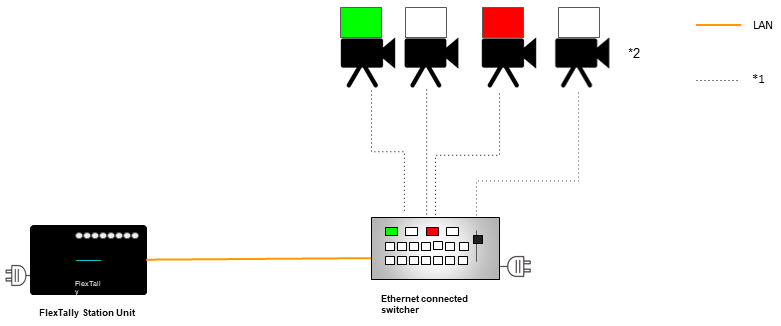
*1: For the cable between the camera and switcher, please c-heck the video input/output specifications of your camera and switcher.
*2: Please prepare the required number of cameras.
This connection method can be used with the following switchers.
| Cerevo | LiveWedge |
| Blackmagic Design | ATEM Mini ATEM Mini Pro ATEM Mini Pro ISO ATEM Mini Extreme ATEM Mini Extreme ISO ATEM Television Studio ATEM Television Studio Pro HD ATEM Television Studio Pro 4K ATEM Production Studio 4K ATEM 1M/E Production Studio 4K ATEM 2M/E Production Studio 4K ATEM 4M/E Broadcast Studio 4K |
| NewTek | TriCaster 2 Elite |
2. Connection Method: USB-GPIO Converter for FlexTally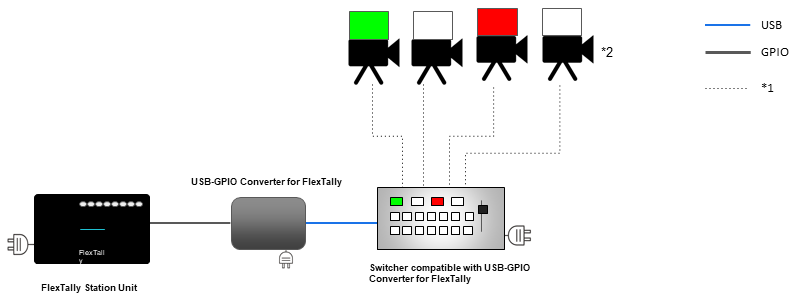
*1: For the cable between the camera and switcher, please check the video input/output specifications of your camera and switcher.
*2: Please prepare the required number of cameras.
This connection method can be used with the following switchers.
| Roland | V-1HD V-1 SDI V-8HD * PST output is not supported. |
| Lumantek | ez-Pro VS4 |
For any questions or to place an order for the USB-GPIO Converter for FlexTally, please contact us.
3. Connection Method: GPIO Cable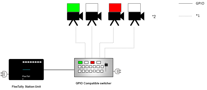
*1: For the cable between the camera and switcher, please check the video input/output specifications of your camera and switcher.
*2: Please prepare the required number of cameras.
This connection method can be used with the following switchers.
| Roland | V-1HD+ V-800HD V-1200HD V-60HD V-800HD MK-2 VR-4HD V-160HD |
| SONY | MCX-500 |
| NewTek | TriCaster TC1 TriCaster460 Tricaster TC410 |
| Panasonic | AG-HMX100 AW-HS50 |
| DataVideo | SE-1200MU |
| FOR-A | HVS-XT100/110 |
(We are not going to say anything about a customized GPIO cable order since it is too much work & small profit for Cerevo)
9.USB-GPIO Converter for FlexTally
This document includes instructions for use and important points for the USB-GPIO Converter for FlexTally, so please make sure to read these instructions before use.
Package Contents
- USB-GPIO Converter for FlexTally
- Quick Set-up Guide / Warranty
- USB cable (Micro B to Type A)
Precautions for Use
Make sure to follow the precautions below when using this product.
- This product does not work as a stand-alone item. You will need FlexTally, a switcher that is compatible with this product, a connection cable and other items. Please buy these separately according to how you will use this product.
- Do not apply excessive force to the cable or connector. Doing so may damage the product.
- This product is precision equipment, beware of impacts during transport or shocks from letting this product fall, which may cause damage.
- The guaranteed working temperature for this product is between 5℃ and 35℃. Do not use this product in an environment with temperatures outside the guaranteed working range. Also, do not use this product in places exposed to direct sunlight or with high levels of humidity. Doing so may cause damage to this product.
- This product is not water- or dust-proof. Take care that no liquids, sand, dust, etc., get into the terminal parts or the interior of the product.
- If you notice any irregularities like strange noises, strange smells, extensive heat generation, the product catching fire, a change in color etc., while using this product, immediately stop using it and contact Cerevo Customer Support.
- Any damage to this product will be handled according to the warranty included in Quick Setup Guide. Please read the warranty carefully before use and contact Cerevo Customer Support if you have any questions.
Supported Switchers
The USB-GPIO converter supports the following switchers. (Last update May 2021)
- Roland V-8HD
- PST (Preset) output is not supported.
- V-8HD Remote is not supported.
- Roland V-1HD
- Roland V-1 SDI
- Lumantek ez-Pro VS4
Instructions for Use
Setup Movie
Preparing FlexTally
In order to use this product, place DIP switches 1 and 2 on the back side of the FlexTally station unit into the OFF position.
The positions of switches 3 to 8 depend on how you using FlexTally. Please refer to this link for the settings of switches 3 to 8.
How to Connect
●When using your switcher via unit operation
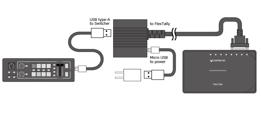
- Please note the USB cable to connect between a switcher and USB-GPIO Converter for FlexTally is not included.
●When using your switcher via iPad app
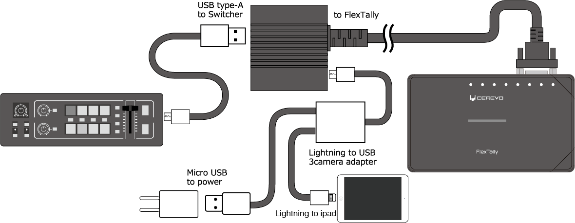
- Please note Lightning to USB 3 camera adapter is not included.
●When using your switcher via PC app
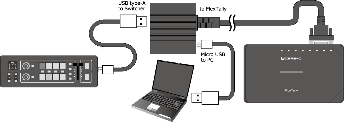
- Please note the USB cable to connect between a PC and USB-GPIO Converter for FlexTally is not included.
Station Setting
●Roland V-1HD, Roland V-1 SDI, Lumantek ez-Pro VS4
The DIP switch settings for the station are GPIO and Type 2.
●Roland V-8HD
The DIP switch settings for the station are GPIO, Type 2, and No.8.
* Must be compatible with Switcher Ver. 1.0.4 or later. If you are using an older version, please follow Roland’s instructions for updating, and be sure to perform a factory reset before using it.
* PST (Preset) output is not supported.